We continue the series of publications prepared by the interactive popular science blog “I’ll Explain in Two Minutes.” The blog talks about simple and complex things that surround us every day and do not raise any questions until we think about them. For example, there you can find out how spaceships do not miss and do not collide with the ISS when docking.
1. It is impossible to sail strictly against the wind. However, if the wind is blowing from the front, but slightly at an angle, the yacht may well move. In such cases, the ship is said to be sailing on a sharp course.

2. The thrust of a sail is generated by two factors. Firstly, the wind simply presses on the sails. Secondly, the oblique sails installed on most modern yachts, when air flows around them, work like an airplane wing and create “lifting force”, only it is directed not upward, but forward. Due to the peculiarities of aerodynamics, the air from the convex side of the sail moves faster than from the concave side, and the pressure from outside There are fewer sails than with the inner one.

3. The total force created by the sail is directed perpendicular to the canvas. According to the rule of vector addition, it is possible to distinguish the drift force (red arrow) and the traction force (green arrow).

4. On sharp courses, the drift force is great, but it is countered by the shape of the hull, keel and rudder: the yacht cannot go sideways due to water resistance. But it willingly slides forward even with a small traction force.

5. To sail strictly against the wind, the yacht tacks: it turns to the wind first on one side or the other, moving forward in segments - tacks. How long the tacks should be and at what angle to the wind should be - important issues of skipper tactics.

6. There are five main courses of a ship relative to the wind. Thanks to Peter I, Dutch maritime terminology took root in Russia.

7. Leventik- the wind blows directly at the bow of the ship. It is impossible to sail this way, but turning to the wind is used to stop the yacht.

8. Closed wind- the same acute course. When you go close-hauled, the wind blows in your face, so it seems that the yacht is developing a very high speed. In fact, this feeling is deceptive.
9. Gulfwind- the wind blows perpendicular to the direction of movement.

10. Backstay- the wind blows from the stern and from the side. This is the fastest course. Fast racing boats sailing backstayed are able to accelerate to speeds exceeding the speed of the wind due to the lifting force of the sail.

11. Fordewind- the same tailwind blowing from the stern. Contrary to expectations, it is not the fastest course: here the lifting power of the sail is not used, and the theoretical speed limit does not exceed the speed of the wind. An experienced skipper can predict invisible air currents just like an airplane pilot can predict updrafts and downdrafts.

You can view an interactive version of the diagram on the “I’ll Explain in Two Minutes” blog.
Courses relative to the wind. Modern yachts and sailing boats are in most cases equipped with oblique sails. Their distinctive feature is that the main part of the sail or all of it is located behind the mast or forestay. Due to the fact that the leading edge of the sail is pulled tightly along the mast (or by itself), the sail flows around the air flow without flushing when it is positioned at a fairly acute angle to the wind. Thanks to this (and with appropriate hull contours), the ship acquires the ability to move at an acute angle to the direction of the wind.
In Fig. 190 shows the position of the sailboat at different courses relative to the wind. An ordinary sailboat cannot sail directly against the wind - the sail in this case does not create a traction force capable of overcoming the resistance of water and air. The best racing yachts in medium winds can sail close-hauled at an angle of 35-40° to the wind direction; Usually this angle is not less than 45°. Therefore, the sailboat is forced to get to a target located directly against the wind. tacking- alternately starboard and port tack. The angle between the ship's courses on one tack and the other is called tacking angle, and the position of the vessel with its bow directly against the wind is leftist. The ability of a ship to tack and move at maximum speed directly into the wind is one of the main qualities of a sailboat.
Courses from close-hauled to halfwind, when the wind blows at 90° to the ship's port, are called sharp; from gulfwind to jibe (the wind blows directly astern) - full. Distinguish steep(course relative to the wind 90-135°) and full(135-180°) backstays, as well as close-hauled (40-60° and 60-80° to the wind, respectively).
Rice. 190. Courses of a sailing ship relative to the wind.
1 - steep close-hauled; 2 - full close-hauled; 3 - gulfwind; 4 - backstay; 5 - jibe; 6 - leftist.
Apparent wind. The air flow that flows around the sails of the yacht does not coincide with the direction true wind(relative to sushi). If the ship is moving, then a counter flow of air appears, the speed of which is equal to the speed of the ship. When there is wind, its direction relative to the ship is deviated in a certain way due to the oncoming air flow; the magnitude of the speed also changes. Thus, the total flow, called apparent wind. Its direction and speed can be obtained by adding the vectors of the true wind and the oncoming flow (Fig. 191).

Rice. 191. Apparent wind at various courses of the yacht relative to the wind.
1 - close-hauled; 2 - gulfwind; 3 - backstay; 4 - jibe.
v- speed of the yacht; v and - true wind speed; v in - speed apparent wind.
It is obvious that on a close-hauled course the apparent wind speed is the greatest, and on a gybe it is the smallest, since in the latter case the speeds of both flows are directed in exactly opposite directions.
The sails on a yacht are always set in the direction of the apparent wind. Note that the speed of the yacht does not grow in direct proportion to the wind speed, but much more slowly. Therefore, when the wind increases, the angle between the direction of the true and apparent wind decreases, and in weak winds, the speed and direction of the apparent wind differs more noticeably from the true one.
Since the forces acting on a sail as on a wing increase in proportion to the square of the speed of the flow, sailboats with minimal resistance to movement may experience a “self-acceleration” phenomenon, in which their speed exceeds the speed of the wind. These types of sailboats include ice yachts - ice boats, hydrofoil yachts, wheeled (beach) yachts and proa - narrow single-hull vessels with an outrigger float. Some of these types of vessels have recorded speeds up to three times the wind speed. So, our national iceboat speed record is 140 km/h, and it was set in a wind whose speed did not exceed 50 km/h. We note in passing that absolute record sailing speeds on water are significantly lower: it was installed in 1981 on a specially built two-masted catamaran “Crossbau-II” and is equal to 67.3 km/h.
Conventional sailing ships, unless they are designed for planing, rarely exceed the displacement speed limit of v = 5.6 √L km/h (see Chapter I).
Forces acting on a sailing ship. There is a fundamental difference between the system of external forces acting on a sailing vessel and a vessel driven by a mechanical engine. On a motorized vessel, the thrust of the propeller - the propeller or water jet - and the force of water resistance to its movement act in the underwater part, located in the center plane and at a small distance from each other vertically.
On a sailboat, the driving force is applied high above the surface of the water and, therefore, above the line of action of the drag force. If the ship moves at an angle to the direction of the wind - close-hauled, then its sails operate according to the principle of an aerodynamic wing, discussed in Chapter II. When air flows around a sail, a vacuum is created on its leeward (convex) side, and increased pressure is created on the windward side. The sum of these pressures can be reduced to the resulting aerodynamic force A(see Fig. 192), directed approximately perpendicular to the chord of the sail profile and applied at the center of sail (CS) high above the water surface.

Rice. 192. Forces acting on the hull and sails.
According to the third law of mechanics, during steady motion of a body in a straight line, each force applied to the body (in this case, to the sails connected to the hull of the yacht through the mast, standing rigging and sheets) must be counteracted by a force equal in magnitude and oppositely directed. On a sailboat this force is the resultant hydrodynamic force H, attached to the underwater part of the hull (Fig. 192). Thus, between the forces A And H there is a known distance - the shoulder, as a result of which a moment of a pair of forces is formed, tending to rotate the ship relative to an axis oriented in a certain way in space.
To simplify the phenomena that occur during movement sailing ships, hydro- and aerodynamic forces and their moments are decomposed into components parallel to the main coordinate axes. Guided by Newton's third law, we can write out in pairs all the components of these forces and moments:
| A | - aerodynamic resultant force; |
| T | - the thrust force of the sails moving the ship forward: |
| D | - heeling force or drift force; |
| A v | - vertical (trimming to the nose) force; |
| P | - mass force (displacement) of the vessel; |
| M d | - trimming moment; |
| M cr | - heeling moment; |
| M P | - the moment leading to the wind; |
| H | - hydrodynamic resultant force; |
| R | - the force of water resistance to the movement of the vessel; |
| R d | - lateral force or resistance to drift; |
| H v | - vertical hydrodynamic force; |
| γ· V | - buoyancy force; |
| M l | - moment of resistance to trim; |
| M V | - restoring moment; |
| M at | - sinking moment. |
In order for the ship to move steadily along its course, each pair of forces and each pair of moments must be equal to each other. For example, the drift force D and drift resistance force R d create a heeling moment M kr, which must be balanced by the restoring moment M in or moment of lateral stability. This moment is formed due to the action of mass forces P and buoyancy of the vessel γ· V, acting on the shoulder l. The same forces form the moment of resistance to trim or the moment of longitudinal stability M l, equal in magnitude and opposing the trimming moment M d. The terms of the latter are the moments of pairs of forces T - R And A v - H v .
Thus, the movement of a sailing ship on an oblique course to the wind is associated with roll and trim, and the lateral force D, in addition to roll, also causes drift - lateral drift, so any sailing ship does not move strictly in the direction of the DP, like a ship with a mechanical engine, but with a small drift angle β. The hull of a sailboat, its keel and rudder become a hydrofoil, onto which an oncoming flow of water flows at an angle of attack equal to the angle of drift. It is this circumstance that determines the formation of a drift resistance force on the keel of the yacht R d, which is a component of the lift force.
Stability of movement and centering of a sailing vessel. Due to heel, the thrust force of the sails T and resistance force R appear to operate in different vertical planes. They form a pair of forces that bring the ship towards the wind - knocking it off the straight course it is following. This is prevented by the moment of the second pair of forces - heeling D and drift resistance forces R d, as well as a small force N on the steering wheel, which must be applied in order to correct the yacht’s movement along the course.
It is obvious that the vessel’s reaction to the action of all these forces depends both on their magnitude and on the ratio of the arms a And b on which they act. With increasing roll, the arm of the drive pair b also increases, and the leverage of the falling pair a depends on the relative position center of sail(CP - points of application of the resulting aerodynamic forces to the sails) and center of lateral resistance(CBS - points of application of the resulting hydrodynamic forces to the yacht hull).
Accurately determining the position of these points is a rather difficult task, especially when you consider that it changes depending on many factors: the ship's course relative to the wind, the cut and tuning of the sails, the list and trim of the yacht, the shape and profile of the keel and rudder, etc.
When designing and re-equipping yachts, they operate with conventional CPs and CBs, considering them located in the centers of gravity of flat figures, which represent sails set in the DP, and the outlines of the underwater part of the DP with a keel, fins and rudder (Fig. 193). The center of gravity of a triangular sail, for example, is located at the intersection of two medians, and the common center of gravity of the two sails is located on a straight line segment connecting the CP of both sails, and divides this segment in inverse proportion to their area. If the sail has a quadrangular shape, then its area is divided diagonally into two triangles and the CP is obtained as the common center of these triangles.
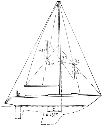
Rice. 193. Determination of the conditional center of sail of a yacht.
The position of the central center can be determined by balancing a template of the underwater profile of the DP, cut out of thin cardboard, on the tip of a needle. When the template is positioned horizontally, the needle will be at the conditional center point. However, this method is more or less applicable for ships with a large area of the underwater part of the wing - for traditional yachts with a long keel line, ship's boats, etc. On modern yachts, the contours of which are designed based on wing theory, the main role in creating the drag force drift is facilitated by a fin keel and a rudder, which is usually installed separately from the keel. The centers of hydrodynamic pressures on their profiles can be found quite accurately. For example, for profiles with a relative thickness δ/ b about 8% this point is at a distance of about 26% of the chord b from the incoming edge.
However, the hull of the yacht in a certain way influences the nature of the flow around the keel and rudder, and this influence varies depending on the roll, trim and speed of the vessel. In most cases, on sharp courses into the wind, the true center of gravity moves forward with respect to the center of pressure determined for the keel and rudder as for isolated profiles. Due to the uncertainty in calculating the position of the CP and the central center, when developing a design for sailing ships, designers place the CP at a certain distance a- ahead - ahead of the Central Bank. The amount of advance is determined statistically, from a comparison with well-proven yachts that have underwater contours, stability and sailing rigs close to the design. The lead is usually set as a percentage of the length of the vessel at the waterline and is 15-18% for a vessel equipped with a Bermuda sloop. L. The less stability of the yacht, the more roll it will receive under the influence of the wind and the greater the advance of the CPU in front of the central steering system is necessary.
Precise adjustment of the relative position of the CP and CB is possible when testing the yacht while underway. If the ship tends to fall into the wind, especially in medium and fresh winds, then this is a major alignment defect. The fact is that the keel deflects the flow of water flowing from it closer to the vessel’s DP. Therefore, if the rudder is straight, then its profile operates with a noticeably lower angle of attack than the keel. If, in order to compensate for the tendency of the yacht to sink, the rudder has to be shifted to the wind, then the lifting force generated on it turns out to be directed in the leeward direction - in the same direction as the drift force D on sails. Consequently, the ship will have increased drift.
Another thing is the easy tendency of the yacht to be driven. The rudder, shifted 3-4° to the leeward side, operates with the same or slightly greater angle of attack as the keel, and effectively participates in resistance to drift. Lateral force H, which occurs on the rudder, causes a significant shift of the general center of gravity towards the stern while simultaneously reducing the drift angle. However, if in order to keep the yacht on a close-hauled course you have to constantly shift the rudder to the leeward side at an angle greater than 2-3°, it is necessary to move the CPU forward or move the central steering system back, which is more difficult.
On a completed yacht, you can move the CPU forward by tilting the mast forward, moving it forward (if the step design allows), shortening the mainsail along the luff, and increasing the area of the main jib. To move the central steering wheel backwards, you need to install a fin in front of the steering wheel or increase the size of the steering blade.
To eliminate the yacht's tendency to sink, it is necessary to apply opposite measures: move the CPU back or move the central center forward.
The role of aerodynamic force components in the creation of thrust and drift. The modern theory of the operation of an oblique sail is based on the provisions of the aerodynamics of the wing, the elements of which were discussed in Chapter II. When an air flow flows around a sail set at an angle of attack α to the apparent wind, an aerodynamic force is created on it A, which can be represented in the form of two components: lift Y, directed perpendicular to the air flow (apparent wind), and drag X- force projections A on the direction of air flow. These forces are used when considering the characteristics of the sail and everything sailing equipment generally.
At the same time force A can be represented in the form of two other components: traction force T, directed along the axis of motion of the yacht, and the drift force perpendicular to it D. Let us recall that the direction of movement of the sailboat (or path) differs from its course by the value of the drift angle β, however, in further analysis this angle can be neglected.
If on a close-hauled course it is possible to increase the lifting force on the sail to the value Y 1, and the frontal resistance remains unchanged, then the forces Y 1 and X, added according to the rule of vector addition, form a new aerodynamic force A 1 (Fig. 194, A). Considering its new components T 1 and D 1, it can be noted that in this case, with an increase in lift, both the thrust force and the drift force increase.

Rice. 194. The role of lift and drag in creating driving force.
With a similar construction, one can be convinced that with an increase in drag on a close-hauled course, the thrust force decreases and the drift force increases. Thus, when sailing close-hauled, the lifting force of the sail plays a decisive role in creating sail thrust; drag should be minimal.
Note that on a close-hauled course the apparent wind has the highest speed, so both components of the aerodynamic force Y And X are quite large.
On a Gulfwind course (Fig. 194, b) lift is the traction force, and drag is the drift force. An increase in the drag of the sail does not affect the amount of traction force: only the drift force increases. However, since the apparent wind speed in the gulfwind is reduced compared to the close-hauled wind, drift affects the ship's performance to a lesser extent.
Backstay on course (Fig. 194, V) the sail operates at high angles of attack, at which the lifting force is significantly less than the drag. If you increase the drag, the thrust and drift force will also increase. As the lifting force increases, the thrust increases and the drift force decreases (Fig. 194, G). Consequently, on the backstay course, an increase in both lift and (or) drag increases thrust.
During a gybe course, the angle of attack of the sail is close to 90°, so the lifting force on the sail is zero, and the drag is directed along the axis of motion of the vessel and is the traction force. The drift force is zero. Therefore, on a gybe course, to increase the thrust of the sails, it is advisable to increase their drag. On racing yachts this is done by setting additional sails - a spinnaker and a blooper, which have a large area and a poorly streamlined shape. Note that on a gybe course, the yacht's sails are affected by the apparent wind of minimum speed, which causes relatively moderate forces on the sails.
Drift resistance. As shown above, the force of drift depends on the yacht's course relative to the wind. When sailing close-hauled, it is approximately three times the thrust force T, moving the ship forward; on gulfwind both forces are approximately equal; on a steep backstay, the sail thrust turns out to be 2-3 times greater than the drift force, and on a pure gybe there is no drift force at all. Consequently, in order for a sailboat to successfully move forward on courses from close-hauled to gulfwind (at an angle of 40-90° to the wind), it must have sufficient lateral resistance to drift, much greater than the resistance of the water to the movement of the yacht along the course.
The function of creating resistance to drift on modern sailing ships is mainly performed by fin keels or centerboards and rudders. The mechanics of the generation of lift on a wing with a symmetrical profile, such as keels, centerboards and rudders, was discussed in Chapter II (see page 67). Note that the drift angle of modern yachts - the angle of attack of the keel or centerboard profile - rarely exceeds 5°, therefore, when designing a keel or centerboard, it is necessary to select its optimal dimensions, shape and cross-sectional profile in order to obtain maximum lifting force with minimal drag. at low angles of attack.
Tests of aerodynamic symmetrical airfoils have shown that thicker airfoils (with a larger cross-sectional thickness ratio t to his chord b) provide greater lifting force than thin ones. However, at low speeds such profiles have higher drag. Optimal results on sailing yachts can be achieved with keel thickness t/b= 0.09÷0.12, since the lifting force on such profiles depends little on the speed of the vessel.
The maximum thickness of the profile should be located at a distance of 30 to 40% of the chord from the leading edge of the keel profile. The NACA 664‑0 profile also has good qualities with a maximum thickness located at a distance of 50% of the chord from the nose (Fig. 195).

Rice. 195. Profiled keel-fin of a yacht.
| Distance from spout x, % b | ||||||
| 2,5 | 5 | 10 | 20 | 30 | 40 | |
| Ordinates y, % b | ||||||
| NACA-66; δ = 0.05 | 2,18 | 2,96 | 3,90 | 4,78 | 5,00 | 4,83 |
| 2,00 | 2,60 | 3,50 | 4,20 | 4,40 | 4,26 | |
| - | 3,40 | 5,23 | 8,72 | 10,74 | 11,85 | |
| Profile; relative thickness δ | Distance from spout x, % b | |||||
| 50 | 60 | 70 | 80 | 90 | 100 | |
| Ordinates y, % b | ||||||
| NACA-66; δ = 0.05 | 4,41 | 3,80 | 3,05 | 2,19 | 1,21 | 0,11 |
| Profile for centerboards; δ = 0.04 | 3,88 | 3,34 | 2,68 | 1,92 | 1,06 | 0,10 |
| Keel of yacht NACA 664-0; δ = 0.12 | 12,00 | 10,94 | 8,35 | 4,99 | 2,59 | 0 |
For lightweight racing dinghies capable of planing and reaching high speeds, centerboards and rudders with a thinner profile are used ( t/b= 0.044÷0.05) and geometric elongation (deepening ratio d to the middle chord b Wed) to 4.
The elongation of the keels of modern keel yachts ranges from 1 to 3, the rudders - up to 4. Most often, the keel has the form of a trapezoid with an inclined leading edge, and the angle of inclination has a certain effect on the amount of lift and drag of the keel. When extending the keel around λ = 0.6, an inclination of the leading edge of up to 50° can be allowed; at λ = 1 - about 20°; for λ > 1.5, a keel with a vertical leading edge is optimal.
The total area of the keel and rudder to effectively counteract drift is usually taken to be from 1/25 to 1/17 of the area of the main sails.
The movement of a sailing yacht in the wind is actually determined by the simple pressure of the wind on its sail, pushing the ship forward. However, wind tunnel research has shown that sailing upwind exposes the sail to a more complex set of forces.
When the incoming air flows around the concave rear surface of the sail, the air speed decreases, while when flowing around the convex front surface of the sail, this speed increases. As a result, an area of high pressure is formed on the back surface of the sail, and a low pressure area on the front surface. The pressure difference on the two sides of the sail creates a pulling (pushing) force that moves the yacht forward at an angle to the wind.

A sailing yacht located approximately at right angles to the wind (in nautical terminology, the yacht is tacked) moves quickly forward. The sail is subject to pulling and lateral forces. If a sailing yacht sails at an acute angle to the wind, its speed slows down due to a decrease in the pulling force and an increase in the side force. The more the sail is turned towards the stern, the slower the yacht moves forward, in particular due to the large lateral force.

A sailing yacht cannot sail directly into the wind, but it can move forward by making a series of short zigzag movements at an angle to the wind, called tacks. If the wind blows to the left side (1), the yacht is said to be sailing on port tack; if it is blowing to starboard (2), it is said to be sailing on starboard tack. In order to cover the distance faster, the yachtsman tries to increase the speed of the yacht to the limit by adjusting the position of its sail, as shown in the figure below left. To minimize deviation to the side from a straight line, the yacht moves, changing course from starboard tack to port and vice versa. When the yacht changes course, the sail is thrown to the other side, and when its plane coincides with the wind line, it flutters for some time, i.e. is inactive (middle picture below the text). The yacht finds itself in the so-called dead zone, losing speed until the wind again inflates the sail from the opposite direction.
“Tailwind!” - they wish all sailors, and it is completely in vain: when the wind blows from the stern, the yacht is not able to reach maximum speed. Helped me make this diagram Vadim Zhdan, professional skipper, racer, organizer and presenter of yacht regattas. Read the tooltips on the diagram to figure it out.
2. The thrust of a sail is generated due to two factors. Firstly, the wind simply presses on the sails. Secondly, the oblique sails installed on most modern yachts, when air flows around them, act like an airplane wing, only it is directed not upward, but forward. Due to aerodynamics, the air on the convex side of the sail moves faster than on the concave side, and the pressure on the outside of the sail is less than on the inside.
 3. The total force created by the sail is directed perpendicular to the canvas. According to the rule of vector addition, it is possible to distinguish the drift force (red arrow) and the traction force (green arrow).
 5. To sail strictly against the wind, the yacht tacks: it turns to the wind with one side or the other, moving forward in segments - tacks. How long the tacks should be and at what angle to the wind should be - important issues of skipper tactics.
 9. Gulfwind- the wind blows perpendicular to the direction of movement.
 11. Fordewind- the same tailwind blowing from the stern. Contrary to expectations, it is not the fastest course: here the lifting power of the sail is not used, and the theoretical speed limit does not exceed the speed of the wind. An experienced skipper can predict invisible air currents in the same way
Until now, we have considered the effect of only two forces on the yacht—the buoyancy force and the weight force, assuming that it is in equilibrium at rest. But since the yacht uses sails to move forward, a complex system of forces acts on the vessel. It is shown schematically in Fig. 4, where the most typical case of a yacht moving close-hauled is considered.
When an air flow - the wind - flows around the sails, a resulting effect is created on them. aerodynamic force A (see Chapter 2), directed approximately perpendicular to the surface of the sail and applied at the center of sail (CS) high above the surface of the water. According to the third law of mechanics, during steady motion of a body in a straight line, each force applied to the body, in this case to the sails connected to the hull of the yacht through the mast, standing rigging and sheets, must be counteracted by a force equal in magnitude and oppositely directed. On a yacht, this is the resulting hydrodynamic force H applied to the underwater part of the hull. Thus, between these forces there is a known distance-arm, as a result of which a moment of a pair of forces is formed.
Both aero- and hydrodynamic forces turn out to be oriented not in a plane, but in space, therefore, when studying the mechanics of a yacht’s motion, the projections of these forces onto the main coordinate planes are considered. Keeping in mind the mentioned Newton's third law, we write out in pairs all the components of the aerodynamic force and the corresponding hydrodynamic reactions:
In order for the yacht to maintain a stable course, each pair of forces and each pair of moments of forces must be equal to each other. For example, the drift force Fd and the drift resistance force Rd create a heeling moment Mkr, which must be balanced by the righting moment Mv or the moment of lateral stability. MV is formed due to the action of the forces of weight D and the buoyancy of the yacht gV acting on the shoulder l. The same forces of weight and buoyancy form the moment of resistance to trim or the moment of longitudinal stability M l, equal in magnitude and counteracting the trimming moment Md. The terms of the latter are the moments of the pairs forces T-R and Fv-Nv.
Significant amendments are made to the given diagram of the action of forces, especially on light yachts, by the crew. Moving to the windward side or along the length of the yacht, the crew, with their weight, effectively tilts the ship or counteracts its trim towards the bow. In creating the stalling moment Md, the decisive role is played by the corresponding steering deflection.
The aerodynamic lateral force Fd, in addition to roll, causes lateral drift-drift, so the yacht does not move strictly along the DP, but with a small drift angle l. It is this circumstance that causes the formation of a drift resistance force Rd on the keel of the yacht, which is similar in nature to the lift force that arises on the wing of an airplane located at an angle of attack to the oncoming flow. Similar to a wing, a close-hauled sail works on a course, for which the angle of attack is the angle between the chord of the sail and the direction of the apparent wind. Thus, in modern ship theory, a sailing yacht is viewed as a symbiosis of two wings: a hull moving in the water and a sail, which is affected by the apparent wind.
Stability
As we have already said, the yacht is subject to forces and moments of force that tend to tilt it in the transverse and longitudinal directions. The ability of a ship to withstand the action of these forces and return to an upright position after their action ceases is called stability. The most important thing for a yacht is lateral stability.
When a yacht floats without heeling, the forces of gravity and buoyancy, applied respectively in the CG and CV, act along the same vertical. If during a roll the crew or other components of the mass load do not move, then for any deviation the CG retains its original position in the DP (point G in Fig. 5), rotating with the ship. At the same time, due to the changed shape of the underwater part of the hull, the CV shifts from point C o towards the heeled side to position C 1. Thanks to this, a moment of a couple of forces arises D and g V s shoulder l, equal to the horizontal distance between the CG and the new CG of the yacht. This moment tends to return the yacht to an upright position and is therefore called restoring.
When rolling, the CV moves along a curved trajectory C 0 C 1, radius of curvature G which is called transverse metacentric radius, r corresponding center of curvature M -transverse metacenter. The value of the radius r and, accordingly, the shape of the curve C 0 C 1 depend on the contours of the body. In general, as the heel increases, the metacentric radius decreases, since its value is proportional to the fourth power of the waterline width.
Obviously, the restoring moment arm depends on the distance GM- elevation of the metacenter above the center of gravity: the smaller it is, the correspondingly smaller the shoulder l during roll. At the very initial stage of the slope of the magnitude GM or h is considered by shipbuilders as a measure of ship stability and is called initial transverse metacentric height. The more h, the greater the heeling force required to tilt the yacht to any specific angle of roll, the more stable the vessel. On cruising and racing yachts, the metacentric height is usually 0.75-1.2 m; on cruising dinghies - 0.6-0.8 m.
Using the GMN triangle, it is easy to determine that the restoring shoulder is . The restoring moment, taking into account the equality of gV and D, is equal to:
Thus, despite the fact that the metacentric height varies within rather narrow limits for yachts of different sizes, the magnitude of the righting moment is directly proportional to the displacement of the yacht, therefore, a heavier vessel is able to withstand a larger heeling moment.
The righting shoulder can be represented as the difference between two distances (see Fig. 5): l f - shape stability shoulder and l b - weight stability shoulder. It is not difficult to establish the physical meaning of these quantities, since l in is determined by the deviation during roll of the line of action of the weight force from the initial position exactly above C 0, and l in is the displacement to the leeward side of the center of the value of the immersed volume of the hull. Considering the action of forces D and gV relative to Co, one can notice that the weight force D tends to heel the yacht even more, and the force gV, on the contrary, tends to straighten the vessel.
By triangle CoGK one can find that , where CoC is the elevation of the CG above the CB in the upright position of the yacht. Thus, in order to reduce the negative effect of weight forces, it is necessary to lower the CG of the yacht if possible. In an ideal case, the CG should be located below the CV, then the weight stability arm becomes positive and the mass of the yacht helps it resist the action of the heeling moment. However, only a few yachts have this characteristic: the deepening of the CG below the CV is associated with the use of very heavy ballast, exceeding 60% of the yacht’s displacement, and excessive lightening of the hull, spars and rigging. An effect similar to a decrease in CG is achieved by moving the crew to the windward side. If we are talking about a light dinghy, then the crew manages to shift the general CG so much that the line of action of the force D intersects with the DP significantly below the CV and the weight stability arm turns out to be positive.
In a keelboat, thanks to the heavy ballast keel, the center of gravity is quite low (most often below the waterline or slightly above it). The yacht's stability is always positive and reaches its maximum at a heel of about 90°, when the yacht lies with its sails on the water. Of course, such a list can only be achieved on a yacht with securely closed openings in the deck and a self-draining cockpit. A yacht with an open cockpit can be flooded with water at a much lower angle of heel (a Dragon class yacht, for example, at 52°) and go to the bottom without having time to straighten out.
In seaworthy yachts, a position of unstable equilibrium occurs at a list of about 130°, when the mast is already under water, being directed downward at an angle of 40° to the surface. With a further increase in the roll, the stability arm becomes negative, the capsizing moment helps to achieve the second position of unstable equilibrium with a roll of 180° (keel up), when the center of gravity turns out to be located high above the center of gravity of a small enough wave so that the ship again takes a normal position - keel down. There are many cases where yachts made a full 360° rotation and retained their seaworthiness.
Comparing the stability of a keel yacht and a dinghy, you can see that the main role in creating the righting moment of a dinghy is played by stability shape, and for a keel yacht - weight stability. That is why there is such a noticeable difference in the contours of their hulls: dinghies have wide hulls with L/B = 2.6-3.2, with a chine of small radius and a large fullness of the waterline. To an even greater extent, the shape of the hull determines the stability of catamarans, in which the volumetric displacement is divided equally between the two hulls. Even with a slight roll, the displacement between the hulls is sharply redistributed, increasing the buoyancy force of the hull immersed in the water (Fig. 6). When the other hull leaves the water (at a list of 8-15°), the stability arm reaches its maximum value - it is slightly less than half the distance between the hulls' DPs. With a further increase in roll, the catamaran behaves like a dinghy whose crew hangs on a trapeze. When the roll is 50-60°, a moment of unstable equilibrium occurs, after which the stability of the catamaran becomes negative.
Static stability diagram. Obviously, a complete characteristic of the stability of a yacht can be the curve of the change in the righting moment Mv depending on the roll angle or static stability diagram (Fig. 7). The diagram clearly distinguishes the moments of maximum stability (W) and the maximum angle of roll at which the ship, left to itself, capsizes (3-sunset angle of the static stability diagram).
Using the diagram, the captain of the ship has the opportunity to assess, for example, the ability of the yacht to carry a particular windage in a wind of a certain strength. To do this, curves of changes in the heeling moment Mkr depending on the roll angle are plotted on the stability diagram. Point B of the intersection of both curves indicates the angle of heel that the yacht will receive under static wind action with a smooth increase. In Fig. 7, the yacht will receive a list corresponding to point D - about 29°. For vessels with clearly defined downward branches of the stability diagram (dinghies, compromises and catamarans), navigation can only be allowed at heel angles not exceeding the maximum point on the stability diagram.
 |
| Rice. 7. Diagram of static stability of a cruising-racing yacht |
In practice, yacht crews often have to deal with the dynamic action of external forces, in which the heeling moment reaches a significant value in a relatively short period of time. This happens when there is a squall or a wave hitting the windward chine. In these cases, not only the magnitude of the heeling moment is important, but also the kinetic energy imparted to the vessel and absorbed by the work of the righting moment.
On the static stability diagram, the work of both moments can be represented in the form of areas enclosed between the corresponding curves and ordinate axes. The condition for the equilibrium of the yacht under the dynamic influence of external forces will be the equality of the areas of OABVE (work Mkr) and OBGVE (work Mv). Considering that the areas of OBVE are common, we can consider the equality of the areas of OAB and BGV. In Fig. 7 it can be seen that in the case of dynamic wind action, the roll angle (point E, about 62°) is noticeably higher than the roll from wind of the same strength during its static action.
From the static stability diagram it can be determined maximum dynamic heeling a moment that capsizes a dinghy or threatens the safety of a yacht with an open cockpit. Obviously, the effect of the restoring moment can only be considered up to the angle of flooding of the cockpit or to the initial point of decrease in the static stability diagram.
It is generally accepted that keel yachts equipped with heavy ballast are practically capsizeable. However, in the already mentioned Fastnet race of 1979, 77 yachts were capsized at a heel angle of more than 90°, and some of them remained afloat with their keels up for some time (from 30 seconds to 5 minutes), and several yachts then rose to their normal position through another board. The most serious damage was the loss of masts (on 12 yachts), batteries, heavy galley stoves and other equipment falling from their sockets. Water getting inside the buildings also led to undesirable consequences. This happened under the dynamic influence of a steep 9-10-meter wave, the profile of which abruptly broke during the transition from the ocean to the shallow Irish Sea, with a wind speed of 25-30 m/s.
Factors affecting lateral stability. Thus, we can draw certain conclusions about the influence of various elements of the yacht design on its stability. At low heel angles, the main role in creating the righting moment is played by the width of the yacht and the fullness coefficient of the waterline area. The wider the yacht and the fuller its waterline, the farther from the DP the center of gravity shifts when the vessel rolls, the greater the shape stability arm. The static stability diagram of a fairly wide yacht has a steeper ascending branch than a narrow one - up to = 60-80°.
The lower the center of gravity of the yacht, the more stable it is, and the influence of deep draft and large ballast affects almost the entire stability diagram of the yacht. When modernizing a yacht, it is useful to remember a simple rule: every kilogram below the waterline improves stability, and every kilogram above the waterline worsens it. The heavy spar and rigging are especially noticeable for stability.
With the same location of the center of gravity, a yacht with excess freeboard also has higher stability at heel angles of more than 30-35°, when on a vessel with a normal side height the deck begins to enter the water. A high-sided yacht has a large maximum righting moment. This quality is also inherent in yachts that have waterproof deckhouses of sufficiently large volume.
Particular attention should be paid to the influence of water in the hold and liquids in tanks. It's not just a matter of moving masses of liquids towards the heeled side; The main role is played by the presence of a free surface of the overflowing liquid, namely its moment of inertia relative to the longitudinal axis. If, for example, the surface of the water in the hold has a length of / and a width of b, then the metacentric height decreases by the amount
, m. (9)
Water in the hold, the free surface of which has a large width, is especially dangerous. Therefore, when sailing in stormy conditions, water from the hold must be removed in a timely manner.
To reduce the influence of the free surface of liquids, longitudinal fender bulkheads are installed in tanks, which are divided into several parts along the width. Holes are made in the bulkheads for the free flow of liquid.
Lateral stability and propulsion of the yacht. As the roll increases beyond 10-12°, the resistance of the water to the movement of the yacht increases noticeably, which leads to a loss of speed. Therefore, it is important that when the wind increases, the yacht can maintain effective sail for longer without excessive heeling. Often, even on relatively large yachts, during racing the crew is positioned on the windward side, trying to reduce the list.
How effective it is to move cargo (crew) to one side is easy to imagine using the simplest formula, which is valid for small angles (within 0-10°) of roll;
, (10)
M o-moment, heeling the yacht by 1°;
D- displacement of the yacht, t;
h- initial transverse metacentric height, m.
Knowing the mass of the cargo being moved and the distance of its new location from the DP, it is possible to determine the heeling moment, and dividing it by Mo, get the roll angle in degrees. For example, if on a yacht with a displacement of 7 tons and A = 1 m, five people are located at the side at a distance of 1.5 m from the DP, then the heeling moment they create will give the yacht a roll of 4.5 ° (or reduce the roll to the other side by approximately the same amount ).
Longitudinal stability. The physics of the phenomena occurring during the longitudinal tilt of the yacht is similar to the phenomena during a roll, but the longitudinal metacentric height is comparable in magnitude to the length of the yacht. Therefore, longitudinal inclinations and trim are usually small and are measured not in degrees, but by changes in draft bow and stern. And yet, if all its capabilities are squeezed out of a yacht, one cannot help but take into account the action of the forces that trim the yacht to the bow and move the center of magnitude forward (see Fig. 4). This can be counteracted by moving the crew to the aft deck.
The forces trimming the bow reach their greatest magnitude when sailing in the backstay; on this course, especially in strong winds, the crew should be moved as far aft as possible. On a close-hauled course, the trim moment is small, and it is best for the crew to position themselves near the midships, heeling the ship. On the jibe, the trim moment turns out to be less than on the backstay, especially if the yacht carries a spinnaker and blooper, which provide a certain lift.
For catamarans, the longitudinal metacentric height is comparable to the transverse height, sometimes less. Therefore, the effect of the trim moment, almost imperceptible on a keel yacht, can capsize a catamaran of the same main dimensions.
Accident statistics indicate cases of capsizing over the bow on passing courses of cruising catamarans with high windage.
1.7. Drift resistance
The lateral force Fd (see Fig. 4) not only heels the yacht, it causes lateral drift sag. The strength of the drift depends on the yacht's course relative to the wind. When sailing in a close-hauled direction, it is three times greater than the thrust force moving the yacht forward; in gulfwind both forces are approximately equal to the steep backstay ( true wind about 135° relative to the yacht's course), the driving force turns out to be 2-3 times greater than the drift force, and in a pure gybe there is no drift force at all. Consequently, in order for a vessel to successfully move ahead on a course from close-hauled to gulfwind, it must have sufficient lateral resistance to drift, much greater than the resistance of the water to the movement of the yacht along the course.
The function of creating resistance to drift in modern yachts is performed mainly by centerboards, fin keels and rudders.
As we have already said, an indispensable condition for the emergence of a force of resistance to drift is the movement of the yacht at a small angle to the DP - the drift angle. Let us consider what happens in the water flow directly at the keel, which is a wing with a cross section in the form of a thin symmetrical aerodynamic profile (Fig. 8).
If there is no drift angle (Fig. 8, a), then the water flow, meeting the keel profile at the point a, is divided into two parts. At this point, called the critical point, the flow speed is equal to O, the pressure is maximum, equal to the velocity head, where r is the mass density of water (for fresh water); v- speed of the yacht (m/s). Both the upper and lower parts of the flow simultaneously flow around the surface of the profile and meet again at the point b on the outgoing edge. Obviously, no force directed across the flow can arise on the profile; Only one frictional resistance force will act, due to the viscosity of water.
If the profile is deviated by a certain angle of attack a(in the case of a yacht keel - the drift angle), then the flow pattern around the profile will change (Fig. 8, b). Critical point A will move to the lower part of the “nose” of the profile. The path that a water particle must travel along the top surface of the profile will lengthen, and the point b 1 where, according to the conditions of flow continuity, particles flowing around the upper and lower surfaces of the profile should meet, having passed an equal path, they end up on the upper surface. However, when going around the sharp outgoing edge of the profile, the lower part of the flow breaks off from the edge in the form of a vortex (Fig. 8, c and d). This vortex, called the starting vortex, rotating counterclockwise, causes water to circulate around the profile in the opposite direction, i.e. clockwise (Fig. 8, d). This phenomenon, caused by viscous forces, is similar to the rotation of a large gear (circulation) meshed with a small drive gear (starting vortex).
After circulation occurs, the starting vortex breaks away from the emerging edge, point b 2 moves closer to this edge, as a result of which there is no longer a difference in the speeds with which the upper and lower parts of the flow leave the wing. The circulation around the wing causes the appearance of a lifting force Y, directed across the flow: at the upper surface of the wing the speed of water particles increases due to circulation, at the lower surface, when encountering particles involved in the circulation, it slows down. Accordingly, at the upper surface the pressure decreases compared to the pressure in the flow in front of the wing, and at the lower surface it increases. The pressure difference gives lift Y.
In addition, the force will act on the profile frontal(profile) resistance X, arising due to friction of water on the surface of the profile and hydrodynamic pressure on its front part.
In Fig. Figure 9 shows the results of measuring pressure at the surface of a symmetrical profile made in a wind tunnel. The y-axis shows the value of the coefficient WITH p, which is the ratio of excess pressure (total pressure minus atmospheric pressure) to velocity head. On the upper side of the profile the pressure is negative (vacuum), on the lower side it is positive. Thus, the lift force acting on any profile element is the sum of the pressure and rarefaction forces acting on it, and in general it is proportional to the area enclosed between the pressure distribution curves along the profile chord (shaded in Fig. 9).
The data presented in Fig. 9 allow us to draw a number of important conclusions about the operation of a yacht keel. Firstly, the main role in creating the lateral force is played by the vacuum that occurs on the surface of the fin from the windward side. Secondly, the peak of rarefaction is located near the incoming edge of the keel. Accordingly, the point of application of the resulting lift force is on the front third of the fin chord. In general, the lift increases up to an angle of attack of 15-18°, after which it suddenly drops.
Due to the formation of vortices on the rarefaction side, the smooth flow around the wing is disrupted, the rarefaction drops and the flow stalls (this phenomenon is discussed in more detail in Chapter 2 for sails). Simultaneously with the increase in the angle of attack, the drag increases; it reaches a maximum at a = 90°.
The drift of a modern yacht rarely exceeds 5°, so there is no need to worry about the flow breaking off the keel. However, the critical angle of attack must be taken into account for yacht rudders, which are also designed and operate on the principle of a wing.
Let's consider the main parameters of yacht keels, which have a significant impact on their effectiveness in creating force to resist drift. Equally, what is stated below can be extended to rudders, taking into account the fact that they operate with a significantly larger angle of attack.
Thickness and cross-sectional shape of the keel. Tests of symmetrical airfoils have shown that thicker airfoils (with a larger cross-sectional thickness ratio t to his chord b) give greater lifting force. Their drag is higher than that of profiles with a smaller relative thickness. Optimal results can be obtained when t/b = 0.09-0.12. The amount of lift on such profiles depends relatively little on the speed of the yacht, so the keels develop sufficient resistance to drift even in light winds.
The position of the maximum profile thickness along the chord length has a significant influence on the magnitude of the drift resistance force. The most effective are profiles whose maximum thickness is located at a distance of 40-50% of the chord from their “nose”. For yacht rudders operating at high angles of attack, profiles with a maximum thickness located somewhat closer to the leading edge are used - up to 30% of the chord.
The shape of the “nose” of the profile—the radius of rounding of the incoming edge—has a certain influence on the efficiency of the keel. If the edge is too sharp, then the flow flowing onto the keel receives great acceleration here and breaks away from the profile in the form of vortices.
In this case, a drop in lift occurs, especially significant at high angles of attack. Therefore, such a sharpening of the incoming edge is unacceptable for rudders.
Aerodynamic extension. At the ends of the wing, water flows from the area of high pressure to the back of the profile. As a result, vortices are shed from the ends of the wing, forming two vortex streets. A fairly significant part of the energy is spent on their maintenance, forming the so-called inductive reactance. In addition, due to pressure equalization at the ends of the wing, a local drop in lift occurs, as shown in the diagram of its distribution along the length of the wing in Fig. 10.
The shorter the wing length L in relation to its chord b, i.e., the smaller its elongation L/b, the relatively greater the loss of lift and the greater the inductive drag. In aerodynamics, it is customary to estimate the wing aspect ratio using the formula
(where 5 is the wing area), which can be applied to wings and fins of any shape. With a rectangular shape, the aerodynamic aspect ratio is equal to the ratio; for delta wing l = 2Llb.
In Fig. 10 shows a wing composed of two trapezoidal fin keels. On a yacht, the keel is attached with a wide base to the bottom, so here there is no flow of water to the vacuum side and, under the influence of the hull, the pressure on both surfaces is equalized. Without this influence, the aerodynamic aspect ratio could be considered to be twice the ratio of the keel depth to its draft. In practice, this ratio, depending on the size of the keel, the contours of the yacht and the angle of heel, is exceeded only by 1.2-1.3 times.
The influence of the aerodynamic elongation of the keel on the magnitude of the drift resistance force it develops R d can be estimated from the test results of a fin having a profile NACA 009 (t/b=9%) and an area of 0.37 m2 (Fig. 11). The flow speed corresponded to the yacht's speed of 3 knots (1.5 m/s). Of interest is the change in the drift resistance force at an angle of attack of 4-6°, which corresponds to the drift angle of the yacht on a close-hauled course. If you accept the force R d with elongation l = 1 per unit (6.8 at a = 5°), then with an increase in l to 2, the drift resistance increases by more than 1.5 times (10.4 kg), and with l = 3 - exactly doubled (13.6 kg). The same graph can serve for a qualitative assessment of the effectiveness of rudders of various extensions, which operate in the region of large angles of attack.
Thus, by increasing the elongation of the keel fin, it is possible to obtain the required amount of lateral force R d with a smaller keel area and, therefore, with a smaller wetted surface area and water resistance to the movement of the yacht. The keel length on modern cruising and racing yachts averages l = 1-3. The rudder feather, which serves not only to control the vessel, but is also an integral element in creating the resistance of the yacht, has an even greater elongation, approaching l = 4.
Area and shape of the keel. Most often, the dimensions of the keel are determined by statistical data, comparing the designed yacht with well-proven vessels. On modern cruising and racing yachts with a rudder separate from the keel, the total area of the keel and rudder ranges from 4.5 to 6.5% of the sail area of the yacht, and the rudder area is 20-40% of the keel area.
To obtain optimal elongation, the yacht designer strives to adopt the maximum draft allowed by sailing conditions or measurement rules. Most often, the keel has the shape of a trapezoid with an inclined leading edge. As studies have shown, for yacht keels with an aspect ratio of 1 to 3, the angle between the leading edge and the vertical in the range from -8° to 22.5° has virtually no effect on the hydrodynamic characteristics of the keel. If the keel (or centerboard) is very narrow and long, then a slope of the leading edge of more than 15° to the vertical is accompanied by a deviation of the water flow lines down the profile, towards the lower rear corner. As a result, the lift force decreases and the keel drag increases. In this case, the optimal tilt angle is 5° to the vertical.
The amount of lift developed by the keel and rudder is significantly influenced by the quality of its surface finish, especially the leading edge, where the flow around the profile is formed. Therefore, it is recommended to polish the keel and rudder at a distance of at least 1.5% of the profile chord.
Yacht speed. The lift force on any wing is determined by the formula:
![]() (11)
(11)
Сy - lift coefficient, depending on the parameters of the wing - profile shape, aspect ratio, plan outline, as well as on the angle of attack - it increases with increasing angle of attack;
r- mass density of water, ;
V- speed of the flow flowing around the wing, m/s;
S- wing area, m2.
Thus, the force of resistance to drift is a variable value proportional to the square of the speed. At the initial moment of the yacht's movement, for example after a tack, when the ship loses speed, or when moving away from the boom into a downwind, the lifting force on the keel is small. In order for the strength Y equaled the drift force F D the keel should be positioned towards the oncoming flow at a high angle of attack. In other words, the ship begins to move with a large drift angle. As the speed increases, the drift angle decreases until it reaches its normal value - 3-5°.
The captain must take this circumstance into account, providing sufficient space to leeward when accelerating the yacht or after turning onto a new tack. A large initial drift angle must be used to quickly gain speed by slightly pulling the sheets. By the way, this reduces the force of drift on the sails.
It is also necessary to remember the mechanics of the generation of lift, which appears on the fin only after the separation of the starting vortex and the development of stable circulation. On the narrow keel of a modern yacht, circulation occurs faster than on the hull of a yacht with a rudder mounted on the keel, that is, on a wing with a large chord. The second yacht will drift more downwind before the hull becomes effective in preventing the drift.
Controllability
Controllability is the quality of a vessel that allows it to follow a given course or change direction. Only a yacht that reacts appropriately to shifting the rudder can be considered controllable.
Controllability combines two properties of a vessel - heading stability and agility.
Course stability- this is the ability of a yacht to maintain a given straight direction of movement when various external forces act on it: wind, waves, etc. Stability on course depends not only on design features yacht and the nature of the action of external forces, but also on the reaction of the helmsman to the deviation of the vessel from the course, his sense of the rudder.
Let us turn again to the diagram of the action of external forces on the sails and hull of the yacht (see Fig. 4). The relative position of the two pairs of forces is of decisive importance for the stability of the yacht on course. Heeling force F d and drift resistance force R d tend to push the bow of the yacht into the wind, while the second para-thrust force T and resistance to movement R brings the yacht to the wind. It is obvious that the reaction of the yacht depends on the ratio of the magnitude of the forces and shoulders under consideration A And b, on which they act. As the roll angle increases, the arm of the drive pair b also increases. Shoulder of a falling couple A depends on the relative position of the center of sail (CS) - the point of application of the resulting aerodynamic forces to the sails and the center of lateral resistance (CLR) - the point of application of the resulting hydrodynamic forces to the hull of the yacht. The position of these points changes depending on many factors: the course of the yacht relative to the wind, the shape and setting of the sails, the list and trim of the yacht, the shape and profile of the keel and rudder, etc.
Therefore, when designing and re-equipping yachts, they operate with conventional CPs and CBs, considering them located in the centers of gravity of flat figures, which are sails set in the center plane of the yacht, and the underwater outlines of the DP with a keel, fins and rudder (Fig. 12).
It is known that the center of gravity of a triangular sail is located at the intersection of two medians, and the common center of gravity of the two sails is located on a straight line segment connecting the CP of both sails, and divides this segment in inverse proportion to their area. Usually, it is not the actual area of the jib that is taken into account, but the measured area of the forward sail triangle.
The position of the central center can be determined by balancing the profile of the underwater part of the DP, cut from thin cardboard, on the tip of a needle. When the template is positioned strictly horizontally, the needle is located at the conventional point of the central center. Let us recall that in creating the force of resistance to drift, the main role belongs to the fin keel and rudder. The centers of hydrodynamic pressures on their profiles can be found quite accurately, for example, for profiles with a relative thickness t/b at about 8% this point is about 26% of the chord away from the leading edge. However, the hull of the yacht, although it participates in the creation of lateral force to a small extent, makes certain changes in the nature of the flow around the keel and rudder, and it changes depending on the angle of heel and trim, as well as the speed of the yacht. In most cases, on a close-hauled course, the true center of gravity moves forward.
Designers, as a rule, place the CPU at some distance (advanced) in front of the central nervous system. Typically, the lead is specified as a percentage of the length of the vessel at the waterline and is 15-18% for a Bermuda sloop. L kvl.
If the true CP turns out to be located too far ahead of the CS, the yacht on a close-hauled course falls to the wind and the helmsman has to constantly keep the rudder tilted to the wind. If the CP is behind the CB, then the yacht tends to bring itself towards the wind; constant steering is required to keep the boat in check.
The tendency of the yacht to sink is especially unpleasant. In the event of an accident with the rudder, the yacht cannot be brought onto a close-hauled course with the help of sails alone; in addition, it has an increased drift. The fact is that the keel of the yacht deflects the flow of water flowing from it closer to the vessel’s DP. Therefore, if the rudder is straight, it operates at a noticeably lower angle of attack than the keel. If you tilt the rudder to the windward side, then the lifting force generated on it turns out to be directed to the leeward side - in the same direction as the drift force on the sails. In this case, the keel and rudder are “pulled” in different directions and the yacht is unstable on course.
Another thing is the easy tendency of the yacht to be driven. The rudder, shifted at a small angle (3-4°) downwind, operates with the same or slightly larger angle of attack as the keel, and effectively participates in resistance to drift. The lateral force arising on the rudder causes a significant displacement of the overall central steering system towards the stern, at the same time the drift angle decreases, the yacht lies stably on course.
However, if on a close-hauled course the rudder has to be constantly shifted to the wind by a greater amount than 3-4°, you should think about adjusting the relative position of the central steering wheel and the central control unit. On an already built yacht, this is easier to do by moving the CPU forward, installing the mast in the steppe to the extreme bow position or tilting it forward.
The reason for the yacht's drift may also be the mainsail - too "potbellied" or with a rebuilt luff. In this case, an intermediate stay is useful, with which you can bend the mast in the middle part (in height) forward and thereby make the sail flatter, as well as weaken the luff. You can also shorten the length of the mainsail luff.
It is more difficult to move the central steering column to the stern, for which you need to install a stern fin in front of the rudder or increase the area of the rudder blade.
We have already said that as the roll increases, the tendency of the yacht to roll also increases. This occurs not only due to an increase in the arm of the adducting pair of forces - T And R. During a roll, the hydrodynamic pressure in the area of the bow wave increases, which leads to a forward displacement of the central nervous system. Therefore, in a fresh wind, to reduce the tendency of the yacht to drift, you should move the mainsail forward and: take a reef on the mainsail or reef it a little for this course. It is also useful to change the jib to a smaller one, which reduces the list and trim of the yacht on the bow.
An experienced designer when choosing the advance value A usually takes into account the stability of the yacht in order to compensate for the increase in driving moment during heeling: for a yacht with less stability, a large advance value is set, for more stable ships the advance is taken to be minimal.
Well-centered yachts often have increased yaw on the backstay course, when the mainsail pulled aboard tends to turn the yacht with its bow to the wind. This is also helped by a high wave coming from the stern at an angle to the DP. To keep the yacht on course, you have to work hard on the rudder, deflecting it to a critical angle, when the flow from its leeward surface is possible (this usually happens at angles of attack of 15-20°). This phenomenon is accompanied by a loss of lift on the rudder and, consequently, the controllability of the yacht. The yacht can suddenly throw itself sharply into the wind and get a large list, and due to the decrease in the deepening of the rudder blade, air from the surface of the water can break through to the rarefaction side.
The fight against this phenomenon, called broching, forces to increase the area of the rudder feather and its lengthening, to install a fin in front of the rudder, the area of which is about a quarter of the area of the feather. Thanks to the presence of a fin in front of the rudder, a directed flow of water is organized, the critical angles of attack of the rudder are increased, air breakthrough to it is prevented and the force on the tiller is reduced. When sailing in the backstay, the crew should strive to ensure that the spinnaker's thrust is directed as far forward as possible, and not sideways, to avoid excessive heeling. It is also important to prevent the appearance of trim on the nose, which could reduce the depth of the steering wheel. Broaching is also facilitated by the roll of the yacht, which appears as a result of interruptions in the air flow from the spinnaker.
Stability on course, in addition to the considered influence of external forces and the relative position of their points of application, is determined by the configuration of the underwater part of the DP. Previously, for long-distance voyages in open water, preference was given to yachts with a long keel line, as they had greater resistance to turning and, accordingly, stability on course. However, this type of vessel has significant disadvantages, such as a large wetted surface and poor maneuverability. In addition, it turned out that course stability depends not so much on the size of the lateral projection of the DP, but on the position of the steering wheel relative to the central steering system, i.e., on the “lever” on which the steering wheel operates. It is noted that if this distance is less than 25% L kvl , then the yacht becomes yawy and reacts poorly to rudder deflection. At l=40-45% L kvl (see Fig. 12) keeping the vessel on a given course is not difficult.
Agility- the ability of a vessel to change the direction of movement and describe a trajectory under the influence of the rudder and sails. The action of the rudder is based on the same principle of a hydrodynamic wing that was considered for a yacht keel. When the steering wheel is shifted to a certain angle, a hydrodynamic force arises R, one of the components of which N pushes the stern of the yacht in the direction opposite to that in which the rudder is placed (Fig. 13). Under its influence, the ship begins to move along a curved trajectory. At the same time strength R gives the component Q - the drag force that slows down the yacht's progress.
If you fix the rudder in one position, the ship will move approximately in a circle called circulation. The diameter or radius of the circulation is a measure of the turning ability of the vessel: the larger the radius of circulation, the worse the turning ability. Only the center of gravity of the yacht moves through the circulation; the stern is carried out. At the same time, the ship experiences drift caused by centrifugal force and partly by force N on the steering wheel.
The radius of circulation depends on the speed and mass of the yacht, its moment of inertia relative to the vertical axis passing through the CG, on the efficiency of the rudder - the magnitude of the force N and its shoulder relative to the CG for a given rudder deflection. The greater the speed and displacement of the yacht, the more heavy masses (engine, anchors, equipment parts) are located at the ends of the vessel, the larger the circulation radius. Usually the radius of circulation, determined during sea trials of the yacht, is expressed in hull lengths.
The agility is better the shorter the underwater part of the vessel and the closer to the midship its main area is concentrated. For example, vessels with a long keel line (such as naval boats) have poor turning ability and, conversely, good turning ability - dinghies with narrow, deep centerboards.
The effectiveness of the rudder depends on the area and shape of the feather, cross-sectional profile, aerodynamic aspect ratio, type of installation (on the sternpost, separate from the keel or on the fin), and also the distance of the stock from the central steering column. The most widespread are rudders designed in the form of a wing with an aerodynamic cross-section profile. Maximum thickness profile is usually taken within 10-12% of the chord and is located 1/3 of the chord from the leading edge. The rudder area is usually 9.5-11% of the area of the submerged part of the yacht's DP.
A rudder with a large aspect ratio (the ratio of the square of the depth of the rudder to its area) develops a large lateral force at low angles of attack, due to which it effectively participates in providing lateral resistance to drift. However, as shown in Fig. 11, at certain angles of attack of profiles of different aspect ratios, the flow is separated from the rarefaction surface, after which the lifting force on the profile drops significantly. For example, when l= 6 critical rudder angle is 15°; at l=2- 30°. As a compromise, handlebars with extensions are used l = 4-5 (the aspect ratio of the rectangular steering wheel is 2-2.5), and to increase the critical shift angle, a skeg fin is installed in front of the steering wheel. A rudder with a large aspect ratio reacts faster to shifting, since the flow circulation, which determines the lifting force, develops faster around a profile with a small chord than around the entire underwater part of the hull with a rudder mounted on the sternpost.
The upper edge of the steering wheel must fit tightly to the body within working deviations of ±30° to prevent water from flowing through it; otherwise, the steering performance will deteriorate. Sometimes, on the rudder bar, if it is mounted on the transom, an aerodynamic washer is attached in the form of a wide plate near the waterline.
What has been said about the shape of the keels also applies to the rudders: a trapezoidal shape with a rectangular or slightly rounded lower edge is considered optimal. To reduce the forces on the tiller, the steering wheel is sometimes made of a balancing type, with an axis of rotation located 1/4-1/5 of the chord from the “nose” of the profile.
When steering a yacht, it is necessary to take into account the specifics of the steering wheel in various conditions, and above all, the disruption of the flow from its back. You cannot make sudden shifts of the steering wheel on board at the beginning of a turn; the flow will stall, lateral force will occur. N on the steering wheel will fall, but the resistance force will quickly increase R. The yacht will enter the circulation slowly and with a large loss of speed. It is necessary to start a turn by shifting the rudder to a small angle, but as soon as the stern rolls outward and the angle of attack of the rudder begins to decrease, it should be shifted to a larger angle relative to the yacht's DP.
It should be remembered that the lateral force on the rudder increases rapidly as the speed of the yacht increases. In a light wind, it is useless to try to turn the yacht quickly by shifting the rudder to a large angle (by the way, the value of the critical angle depends on the speed: at lower speeds, flow separation occurs at lower angles of attack).
The resistance of the rudder when the yacht's course changes, depending on its shape, design and location, ranges from 10 to 40% of the total resistance of the yacht. Therefore, the technique of steering the rudder (and the centering of the yacht, on which stability on course depends) must be taken very seriously, and the rudder must not be allowed to deviate at a greater angle than necessary.
Sales rate
Sales rate refers to the ability of a yacht to reach a certain speed while efficiently using wind energy.
The speed that a yacht can reach depends primarily on the wind speed, since all the aerodynamic forces acting on the sails. including the traction force, increase in proportion to the square of the apparent wind speed. In addition, it also depends on the power supply of the vessel - the ratio of the sail area to its dimensions. The ratio most often used as a characteristic of energy availability is S" 1/2 /V 1/3(where S is the windage area, m2; V- total displacement, m 3) or S/W (here W is the wetted surface of the hull, including the keel and rudder).
The thrust force, and therefore the speed of the yacht, is also determined by the ability of the sailing rig to develop sufficient thrust at various courses relative to the wind direction.
The listed factors relate to the yacht’s propulsion sails, which convert wind energy into motive force T. As shown in Fig. 4, this force during uniform motion of the yacht must be equal and opposite to the force of resistance to movement R. The latter is a projection of the resulting all hydrodynamic forces acting on the wetted surface of the body onto the direction of movement.
There are two types of hydrodynamic forces: pressure forces directed perpendicular to the surface of the body, and viscous forces acting tangentially to this surface. The resultant of the viscous forces gives the force friction resistance.
Pressure forces are caused by the formation of waves on the surface of the water when the yacht moves, so their resulting force gives wave resistance.
With a large curvature of the hull surface in the aft part, the boundary layer can come off from the skin, and vortices can form, absorbing part of the energy of the driving force. This creates another component of resistance to the movement of the yacht - shape resistance.
Two more types of resistance appear due to the fact that the yacht does not move straight along the DP, but with a certain drift angle and roll. This inductive and heel resistance. A significant share in the inductive resistance is occupied by the resistance of the protruding parts - the keel and rudder.
Finally, the forward movement of the yacht is also resisted by the air washing the hull, the crew, and the development of the system of rigging cables and sails. This piece of resistance is called air.
Friction resistance. When the yacht moves, water particles directly adjacent to the hull skin seem to stick to it and are carried along with the ship. The speed of these particles relative to the body is zero (Fig. 14). The next layer of particles, sliding over the first, already lags slightly behind the corresponding points of the hull, and at a certain distance from the hull the water generally remains motionless or has a speed relative to the hull equal to the speed of the yacht v. This layer of water, in which viscous forces act, and the speed of movement of water particles relative to the hull increases from 0 to the speed of the ship, is called the boundary layer. Its thickness is relatively small and ranges from 1 to 2% of the hull length along the waterline, however, the nature or mode of movement of water particles in it has a significant impact on the amount of friction resistance.
It has been established that the mode of movement of the chasgitz varies depending on the speed of the vessel and the length of its wetted surface. In hydrodynamics, this dependence is expressed by the Reynolds number:
n is the coefficient of kinematic viscosity of water (for fresh water n = 1.15-10 -6 m 2 /s);
L- wetted surface length, m;
v- yacht speed, m/s.
With a relatively small number Re = 10 6, water particles in the boundary layer move in layers, forming laminar flow. Its energy is not enough to overcome the viscous forces that prevent the transverse movements of particles. The greatest difference in velocity between layers of particles occurs directly at the surface of the housing; Accordingly, the friction forces are greatest here.
The Reynolds number in the boundary layer increases as water particles move away from the stem (with increasing wetted length). At a speed of 2 m/s, for example, already at a distance of about 2 m from it Re will reach a critical value at which the flow regime in the boundary layer becomes vortex, i.e. turbulent and directed across the boundary layer. Due to the resulting exchange of kinetic energy between the layers, the speed of particles near the surface of the housing increases to a greater extent than with laminar flow. Speed difference Dv here the friction resistance increases accordingly. Due to the transverse movements of water particles, the thickness of the boundary layer increases, and the friction resistance increases sharply.
The laminar flow regime covers only a small part of the yacht's hull in the bow part and only at low speeds. Critical value Re, at which turbulent flow around the body occurs, lies in the range of 5-10 5-6-10 6 and largely depends on the shape and smoothness of its surface. As the speed increases, the point of transition of the laminar boundary layer into the turbulent one moves towards the nose and at a sufficiently high speed there may come a moment when the entire wetted surface of the hull will be covered by a turbulent flow. True, directly near the skin, where the flow velocity is close to zero, a thin film with a laminar regime—a laminar sublayer—still remains.
Friction resistance is calculated using the formula:
![]() (13)
(13)
R tr - friction resistance, kg;
ztr - friction resistance coefficient;
r-mass density of water;
for fresh water:
v- yacht speed, m/s;
W-wetted surface, m2.
The friction drag coefficient is a variable value depending on the nature of the flow in the boundary layer and the length of the body L kvl of speed v and surface roughness of the housing.
In Fig. Figure 15 shows the dependence of the friction resistance coefficient ztr on the number Re and surface roughness of the housing. The increase in resistance of a rough surface compared to a smooth one can easily be explained by the presence of a laminar sublayer in the turbulent boundary layer. If the tubercles on the surface are completely immersed in the laminar sublayer, then they do not introduce significant changes into the nature of the laminar flow of the sublayer. If the irregularities exceed the thickness of the sublayer and protrude above it, then turbulization of the movement of water particles occurs throughout the thickness of the boundary layer, and the friction coefficient increases accordingly.
Rice. 15 allows us to appreciate the importance of finishing the bottom of a yacht to reduce its frictional resistance. For example, if a yacht with a length of 7.5 m along the waterline moves at a speed v= 6 knots (3.1 m/s), then the corresponding number
![]()
Let us assume that the bottom of the yacht has roughness (average height of irregularities) k== 0.2 mm, which corresponds to relative roughness
L/k = 7500/0.2 = 3.75 10 4. For a given roughness and number R e the friction coefficient is equal to z tr = 0.0038 (point G).
Let us evaluate whether it is possible to obtain in this case a bottom surface that is close to technically smooth. At R e = 2-10 7 such a surface corresponds to the relative roughness L/k= 3 10 5 or absolute roughness k=7500/3 10 5 = 0.025 mm. Experience shows that this can be achieved by carefully sanding the bottom with fine sandpaper and then varnishing it. Will the effort be worth it? The graph shows that the friction drag coefficient will decrease to z tr = 0.0028 (point D), or by 30%, which, of course, cannot be neglected by a crew counting on success in racing.
Line B allows you to estimate the permissible bottom roughness for yachts of various sizes and different speeds. It can be seen that with increasing waterline length and speed, the requirements for surface quality increase.
For orientation, we present the roughness values (in mm) for various surfaces:
wooden, carefully varnished and polished - 0.003-0.005;
wooden, painted and sanded - 0.02-0.03;
painted with a patented coating - 0.04-0.C6;
wooden, painted with red lead - 0.15;
regular board - 0.5;
bottom overgrown with shells - up to 4.0.
We have already said that along part of the length of the yacht, starting from the stem, a laminar boundary layer can be maintained, unless excessive roughness contributes to turbulence of the flow. Therefore, it is especially important to carefully process the bow of the hull, all the incoming edges of the keel, fins and rudders. For small transverse dimensions - chords - the entire surface of the keel and rudder should be ground. In the aft part of the hull, where the thickness of the boundary layer increases, the requirements for surface finishing can be somewhat reduced.
The fouling of the bottom with algae and shells has a particularly strong effect on frictional resistance. If you do not periodically clean the bottom of yachts that are constantly in the water, then after two to three months the frictional resistance can increase by 50-80%, which is equivalent to a loss of speed in an average wind of 15-25%.
Form resistance. Even with a well-streamlined hull, while moving, you can detect a wake-stream in which the water makes vortex movements. This is a consequence of the separation of the boundary layer from the body at a certain point (B in Fig. 14). The position of the point depends on the nature of the change in surface curvature along the length of the body. The smoother the contours of the stern end, the further to the stern the separation of the boundary layer occurs and the less vortex formation occurs.
With normal ratios of body length to width, the shape resistance is low. Its increase may be due to the presence of sharp cheekbones, broken hull lines, incorrectly profiled keels, rudders and other protruding parts. The shape resistance increases with a decrease in the extent of the zone, the laminar boundary layer, so it is necessary to remove paint deposits, reduce roughness, seal recesses in the skin, place fairings on protruding pipes, etc.
Wave resistance. The appearance of waves near the hull of a ship during its movement is caused by the action of gravity of the liquid at the interface between water and air. At the bow end, where the hull meets the water, the pressure rises sharply and the water rises to a certain height. Closer to the midsection, where, due to the expansion of the ship's hull, the speed of the flow increases, the pressure in it, according to Bernoulli's law, drops and the water level decreases. In the aft part, where the pressure rises again, a second wave peak forms. Water particles begin to oscillate near the body, which causes secondary oscillations of the water surface.
A complex system of bow and stern waves arises, which is the same in nature for ships of any size (Fig. 16). At low speeds, divergent waves originating in the bow and stern of the ship are clearly visible. Their ridges are located at an angle of 36-40° to the center plane. At higher speeds, transverse waves are released, the crests of which do not extend beyond the sect/era, limited by an angle of 18-20° to the vessel’s DP. The bow and stern systems of transverse waves interact with each other, which can result in both an increase in the height of the total wave behind the stern of the vessel and a decrease in it. As they move away from the ship, the energy of the waves is absorbed by the medium and they gradually attenuate.
The amount of wave resistance varies depending on the speed of the yacht. From the theory of oscillations it is known that the speed of propagation of waves is related to their length l ratio
Where p = 3,14; v- yacht speed, m/s; g = 9.81 m/s 2 - acceleration due to gravity.
Since the wave system moves with the yacht, the speed of wave propagation is equal to the speed of the yacht.
If we are talking, for example, about a yacht with a length along the waterline of 8 m, then at a speed of 4 knots there will be about three transverse waves along the length of the hull, and at a speed of 6 knots - one and a half. The relationship between the transverse wavelength X created by a body of length Lkvl! moving at speed v, largely determines the value of wave resistance.