A Boeing 737 is not a Cessna Skyhawk; piloting it involves a lot of various procedures and management of complex systems.
To fly a Boeing 737, you must learn various key concepts, diagrams, and procedures. Careful planning is the key to successful jet piloting. In this lesson you will take off, perform a simple flight with several turns, descend and land the aircraft. After your first landing of this kind, you will never be the same. No, I don't mean you'll be completely mangled and need a chiropractor. I wanted to say that after this you will have such a wide smile on your face that the neighbors will think that you are showing off your new teeth to them.
Jet Flying Basics
To better understand the principles of piloting a Boeing 737-800 aircraft in the game Flight Simulator, let's study this aircraft and its flight modes in more detail. The information we need covers various airspeed parameters, flight modes and instruments. Below are ordered descriptions of the general stages of flight. For a simplified description of the flight, see the Quick Start section.
Flight profiles
The flight profile is the configuration of the aircraft, which includes speed, engine power, pitch angle, flap angle and landing gear position. The side view of the plane has nothing to do with it. At each individual stage of the flight (take-off, cruise flight, descent, approach and landing), the aircraft is given a specific profile. Precise setting of the profile parameters is the key to a successful flight. Let's take a closer look at each stage of the flight and the configuration used in it.
What is a flight profile?
A flight profile is a predetermined configuration of an aircraft used during a specific phase of flight. The words "preset" mean that the airline or aircraft manufacturer has preset the profile parameters to ensure a safe and controlled flight. Typical phases of flight are takeoff, departure, climb to cruising altitude, commencement of approach and different systems landing approach using instruments for which the aircraft is certified (ILS, VOR, OPRS, GPS, CAT III, etc.).
Profiles help the pilot set up the aircraft's configuration, control it at each point in the flight, and transition from one phase of flight to the next. The actual speeds and masses that the pilot is typically required to look for in the charts are not usually listed in the profile - the "standard" speeds are listed there. To make your training flight easier (and keep your brain from boiling over), the following is the bare minimum of information required. To go to a quick guide for any of the profiles described in this section, select the appropriate link:
Take the time to study each profile (you can even print them out), and then feel free to try out what you've learned in practice. If you feel that you need to better think about your plan of action, do not hesitate to pause the game, otherwise your heart may stop from an overabundance of information. Remember, these profiles are needed to make it easier for you to understand the principles of controlling a Boeing 737-800 in the Flight Simulator game. They do not address all issues, parameters or standard operating procedures of any airline or aircraft manufacturer. Have fun and think about what will happen the next time you take the controls of a commercial airliner.
Takeoff
- Calculation of take-off weight
- Setting the flaps to takeoff position
- Determination of takeoff speed
- Determining the time or speed at which the flaps begin to retract
Cruise flight
- Selecting cruise altitude and speed
(or flying in a circle over the airfield)
Decrease (refer to Lesson 2 for details)
- Choosing the moment to start descending
- Determination of landing mass
- Selection of flap configuration during descent
- Determining approach speed based on weight and conditions
Approach
- Speed control
- Aircraft configuration management
Landing
- Changing the configuration
- Approach using HUD or visual approach
- Sliding along the center line
- Airplane stop
About take-off weight
One of the most important characteristics of the Boeing 737-800 aircraft is its weight. Aircraft weight is taken into account at various stages of flight to determine parameters such as takeoff speed, landing speed, and flap extension and retraction speed. During flight, the plane burns fuel. The more fuel a plane uses, the lighter it becomes. The key point here is that the mass of the aircraft decreases from the beginning to the end of the flight.
First of all you need to know take-off weight And aircraft landing weight. Both of these parameters, combined with outside air temperature and density altitude, are used to determine takeoff and landing speeds. Too difficult? Maybe so, but we'll keep things simple by using certain assumptions and default settings for the Boeing 737-800 in Flight Simulator.
Default operating restrictions for Flight Simulator
You may have noticed that the maximum taxi weight exceeds the maximum takeoff weight. This discrepancy is taken into account the fuel that you will burn while taxiing around the airfield and waiting for your turn to take off.
It is also worth paying attention to the fact that the maximum landing weight is less than the maximum take-off weight. This means you can't just land the plane right after takeoff - it's too heavy, so you have to circle around before landing.
Weight without fuel is the total weight of the aircraft fully loaded with baggage and passengers, but absolutely without fuel. Knowing this mass allows you to determine the actual weight of the aircraft at any given time. To do this, you need to add the mass of the current fuel supply to the mass without fuel.
In Flight Simulator you can easily change the fuel load level. The Boeing 737-800 has three fuel tanks: left, right and center.
The numbers tell us that the total fuel mass is 46,063 lb (20,894 kg). To calculate the weight of the aircraft without fuel (we will use this as a base value later), we subtract the fuel weight from the maximum takeoff weight (174,200 lbs or 79,016 kg) to get 128,137 lbs (58,122 kg).
Flaps on takeoff: retract or extend?
During takeoff, commercial airline pilots use different flap profiles depending on aircraft weight, runway length, temperature, density altitude, and surface conditions. For each set of takeoff conditions, the optimal flap angle is calculated (perhaps airlines hire additional pilots for these calculations). But we will not delve into mathematics, but will release the flaps at an angle of 5 degrees at takeoff and take off using the default game settings.
Takeoff speed control
Determination of takeoff speed
Speed control is very important when flying a Boeing 737. To determine the exact takeoff and landing speeds, you need to look at various tables (like in a mirror, ad nauseam), take into account the aircraft configuration, weight, temperature and density altitude. In this training flight we will take the easy path and set the external conditions equal to the so-called. "standard day".
Speeds in special cases
The three most important speeds for takeoff are V1, Vr and V2. This is the so-called "speeds in special cases." The correct choice of this speed depends on the weight of the aircraft, external conditions and the take-off flap profile. By setting the aircraft's mass to the standard weight for the model in Flight Simulator, standard conditions, and a flap angle of 5 degrees, we can simplify the choice of speeds to a single set of values.
V1 is takeoff decision speed. The length of the runway that ensures a safe takeoff depends on the aircraft's takeoff weight, temperature, and density altitude. Moving in takeoff mode, the aircraft reaches a certain point at which it is necessary to make a decision about takeoff or stop. When piloting a Boeing 737, this point is determined by the aircraft's speed and is designated V1. Before the plane reaches V1 speed, you can, theoretically, reduce the engine speed, apply the brakes and stop within the runway, preventing the plane from becoming an overgrown all-terrain vehicle. Once you exceed the speed of V1, you are doomed to climb. Based on the assumptions made above, we will take the speed V1 in this training flight to be equal to 150 knots.
VR is front landing gear lift speed. At this speed, the pilot takes the helm, raises the nose until the desired pitch angle is created (+20 degrees) and takes off. Let's take the indicated airspeed to be 154 knots as Vr. It should be borne in mind that if you raise the Boeing's nose too high during takeoff, you can accidentally touch the tail with the runway, thereby shortening it slightly. To keep the tail from hitting the ground, increase the pitch gradually, bringing it to 20 degrees no faster than 3 degrees per second.
V2 is minimum safe takeoff speed. Even if the engine fails immediately after reaching V1 speed, the generated thrust will be enough to take off at a given vertical speed and altitude above the terrain. Since takeoff can be performed with different flap configurations, the climb speed for a twin-engine aircraft, considered the minimum acceptable while maintaining controllability, is set to V2+15 knots. This speed is suitable for any takeoff flap configuration.
If you listened to the instructor during takeoff, you heard him report the situation:
Power setting
Now we know how takeoff speed depends on the weight of the aircraft and external conditions. But how to set the engine power so that the plane moves at a given speed?
 Rice. 1-2. Motor indicators |
The power of a turbojet aircraft engine is measured not in absolute number of revolutions per minute, as in piston aircraft, but as a percentage of the maximum number of revolutions, i.e., of the rated power of the engine. The two main power ratings of a Boeing 737-800 engine are the low-pressure turbine shaft speed (N1) and the high-pressure turbine shaft speed (N2).
The value of N1 is measured as %% of the maximum number of revolutions of the low-pressure turbine shaft. This value best describes engine power. It changes by moving the throttle, which allows you to set the desired airspeed.
The N2 value is measured in %% of the maximum number of revolutions of the high-pressure turbine shaft and shows the rotation speed of the compressor blades. This speed should not exceed the maximum permissible design rotation speed. Displaying the N2 value on the indicator allows you to monitor compliance with the limit.
In this training flight we will focus on controlling the N1 value.
Let's take off
Now that we know enough about mass, flap deflection and target airspeeds, we can occupy the runway and take off. You can start your training flight directly from the center line of the departure aerodrome runway or from the loading area, but before that you should set up the radio navigation devices and autopilot, run your eyes through the checklist, set the flaps to 5 degrees, and only then request permission from ATC to taxi and takeoff.
Regardless of how you end up on the runway, it is worth checking and adjusting all equipment, as well as creating a takeoff plan. Typically, to obtain instrument clearance, crews follow a standard departure procedure. The game simplifies the process of revving up and taking off on the runway. The departure always follows a specific pattern, which includes an airspeed limit of 200 knots below 3,000 feet and 250 knots between 3,000 and 10,000 feet.
Takeoff
Airspeed limit
Flight regulations prescribe certain speed limits. By the way, their compliance will be checked during your check flight. When departing from an airfield surrounded by airspace Class B, speed below 10,000 feet must not exceed 250 knots. In Class C and D airspace, the limit narrows to 200 knots (airfield airspace is generally considered to be a radius of 4 miles and an altitude of up to 2,500 feet), and from leaving the airfield until reaching an altitude of 10,000 feet is 250 knots. These limitations are key to understanding the pilot's performance during takeoff. For details please contact Dictionary and articles about air traffic control.
Takeoff clearance
Having adjusted all the instruments and received permission to take off, increase the engine speed to 40-50% of the nominal value, holding the aircraft on the brakes. This procedure serves two purposes. Firstly, you can review the instruments to make sure that they are working and their readings are normal (yes, in addition to the nutritional standards, pilots have other standards). Secondly, the resulting pause gives the engines the opportunity to gain speed to an average level, and you do not risk overheating the brakes while looking at the instruments. After making sure that both engines have the same power and the instrument readings are normal, release the brakes and set the speed to 95 percent of N1. Note that the throttle on this aircraft is much more sensitive than on the Cessna Skyhawk SP or Beechcraft Baron 58. Instead of immediately moving the throttles to full power, set them to three-quarters of the nominal and slowly increase the power until it reaches 95% of N1. Or move the throttle forward all the way, and then reduce the thrust so that it does not exceed 95%.
Now, as the plane accelerates along the runway centerline, you need to monitor its speed. The first boundary speed is the speed of making a decision when there is no turning back. Make sure all appliances are in working order. If so, continue to take off. The next important speed is the front strut lift speed. At 154 knots, take the helm and take off. Bring pitch to +20 degrees with a nose-up rate of approximately 3 degrees per second. It is easy to calculate that it will take approximately 6.5 seconds to achieve this pitch angle.
Parameters are normal - remove the chassis
After reaching a pitch of 20 degrees and leveling the plane's roll, check the variometer and altimeter. If their parameters are normal, it means that the rate of climb is maintained and the landing gear can be retracted. Without the proper rate of climb, this should not be done, since the plane is too close to the ground and can touch the runway again due to wind shear, the rise of the nose gear at too low a speed, an excessively high pitch angle, an alien force field (kidding, kidding) and others reasons. The chassis is retracted using the key G or the corresponding button on the joystick.
Retracting the flaps
During the initial phase of a flight, pilots set the appropriate profile of the aircraft to protect it from collisions with terrain and obstacles, and to ensure sufficient rate of climb in the event of engine failure. To perform this procedure, you must be 400 feet above the ground, with flaps extended to 5 degrees, maintaining a speed of 180 knots. Setting a pitch angle of 20 degrees will help you with this. The second main element of departure is to gain a safe altitude of 1000 feet above ground level with sufficient climb and airspeed. Having reached the specified values, you can proceed to the next takeoff stage.
Once you reach 1,000 feet above ground level, retract the flaps according to the takeoff profile. At this point you should be flying at a speed of V2+15 (162+15), while gaining altitude. Now you can begin retracting the flaps. Reduce the flap angle from 5 to 1 degree by pressing F6 twice. Set the engines power to 90% of nominal, reduce the pitch angle to 15 degrees and pick up speed. Once above 2,500 feet above ground level, reduce pitch to 10-12 degrees and accelerate to 250 knots. When the speed exceeds 200 knots, complete retracting the flaps. It also doesn't hurt to follow the "After Takeoff" checklist.
Cruise flight
Climbing altitude
Maintain a pitch of 10-12 degrees and a speed of 250 knots at 90% of N1 until you climb above 10,000 feet. Then reduce pitch to 6 degrees and increase speed to 280-300 knots. The higher you go, the thinner the air becomes, which affects engine performance. Adjust the thrust so that it remains at 90%. As you gain altitude, you may have to reduce your pitch to 5-6 degrees to maintain the 280 knot speed.
Before reaching cruising altitude 1,000 feet, lower the nose and maintain a vertical speed of 1,500 feet per minute. When you are 150 feet from cruising altitude, begin leveling off by reducing your pitch to 2 degrees while reducing the rpm to 70-72%. Don't forget to level the plane in pitch using the trim tabs. Now you can turn on the autopilot to maintain heading, altitude, and airspeed (although I personally prefer to fly the 737 myself on short flights). On long flights, the autopilot will help you even more than the co-pilot - except maybe serve you coffee.
Decline
We covered the basic steps of takeoff, cruising altitude, and leveling off. Now we need to worry about the descent and how we get to the right place at the right speed and altitude. Descent is the entire focus of Lesson 2, but here we will briefly review your actions on this training flight.
When it's time to descend, you need to perform several important steps to be in the right place at the right time. This is what the aircraft crew must do before the descent begins.
- Plan the moment to start the descent.
- Receive Automatic Information Service (ATIS) reports and other information related to approach and landing.
- Calculate the approximate landing weight of the aircraft.
- Determine the flap position and approach speed.
- Determine the arrival runway and approach route.
- Instruct the crew about the landing approach features.
- Perform control operations of the inspection card in the "Reduction" section.
When should you slow down?
Maintaining speed is very important for piloting. It plays a role at two points: during descent, at the entrance to the denser layers of the atmosphere, and at the leveling off point, where a reduction in speed may be required to comply with the speed limit (for example, the 250 knot limit).
As we descend into the denser layers of the atmosphere, the unit of measurement for indicated speed will again become nautical miles per hour (knots) instead of a percentage of the speed of sound (Mach number). You can determine the transition threshold by a red and white striped bar or arrow. This arrow shows maximum permissible speed airplane. While descending, the striped arrow approaches the airspeed arrow and, if this fact is left unattended, may cross it. This means that the plane has exceeded the permissible speed, which will be indicated by the clicking of the audible alarm (and strange sounds made by the co-pilot). To prevent overspeeding, reduce thrust to 45% and maintain a speed of 310-320 knots for the remaining decrease.
Rice. 1-7. Overspeed indicator |
When descending from cruising altitude, the aircraft retains its driving force - after all, its speed exceeds 300 knots. You don’t need such acceleration at all; the speed should decrease. This is not at all difficult to do; passengers do not even have to stick their hands out of the windows. When planning your descent, add 5 nautical miles to level out and reach the set speed in idle mode (yes, here, unlike the Baron, you can immediately move the throttle to idle without fear of overcooling the engine). The result is something like this: we descend at a speed of about 300 knots, level off at an altitude of about 10,000 feet, set low throttle and coast for about 5 nautical miles until the speed drops to 250 knots. Then we set the thrust to 52-55% and maintain this speed.
As a last resort, you can always use interceptors by releasing and retracting them with a key / . Accurate planning will prepare you well for approach and landing.
Approach planning
Among the information reported by the Automatic Information Service (ATIS), the following are of particular interest: local weather conditions, airfield pressure (at which you will set the altimeter when descending from FL180), operating runway, restrictions on the reception of aircraft, occupied runways and taxiways. This information will help you prepare for your approach.
Landing weight
The descent calculation is usually made 100-120 miles (about 20-25 minutes) before landing. To calculate landing weight, click ALT+A+F and find out your current fuel supply. If you're above 25,000 feet, it's pretty safe to say that you'll burn 1,700 pounds of fuel during your descent, approach, and landing. Subtract 1,700 lbs from the current fuel capacity and then add 100,000 lbs to the result to obtain the approximate landing weight.
Flap position during landing
The landing flap position depends on many factors, such as runway length, approach parameters, runway conditions, weather conditions and fuel efficiency. In order to stay on the easy path, during these training flights we will lower the flaps to 30 degrees on all landings.
Approach speed
During approach and landing, you will constantly reduce airspeed, which should not fall below what is acceptable for your aircraft configuration. A good landing is a soft landing, but if you fly too slowly, the plane will simply flop onto the runway. You now need to maintain the desired airspeed, taking into account the position of the flaps and the weight of the aircraft. At too low a speed, the plane will become difficult to control, or, much worse, will enter a stall and land earlier than desired. Here, as at takeoff, there are certain speeds that ensure optimal flight performance and protect the aircraft from stalling and other unwanted incidents. The airspeed that defines the difference between controllable and less-than-controllable flight is called “weight and conditions approach speed” (Vref).
For greater safety and better flight performance, another 5 knots are added to this speed. Therefore, if the speed determined for a given aircraft landing weight and flap deflection is Vref, the actual approach speed will be Vref+5 knots. In case of strong crosswinds or wind shear, another 10 knots can be added to this value. You probably now remember with fondness the flights on the Skyhawk SP? I understand you. None of this is easy, but that’s how jet aviation is.
When are all these calculations carried out? At the descent planning stage, the crew calculates the landing weight and selects the desired flap angle. Knowing the mass of the aircraft and the deflection of the flaps, the speed Vref can be calculated.
Approach briefing
Now that you know the weather conditions of the airfield, the pressure on it and the working arrival runway, you can prepare for the landing approach. It's time to look at the approach diagram.
It is unlikely that you will now adjust the radio and the input course. These actions are included in the “Approach” section of the checklist. We still need to follow the standard arrival procedure and follow the instructions of the controllers who guide us on the approach path.
Approach
We've covered the principles of descent planning and maintaining speed, now it's time to learn more about the arrival airfield. Lesson 3 covers ILS approaches and covers the basics of landing on a runway. If you have turned on ATC in the game, then you will be “guided” (set a flight course) to the approach trajectory. If you are flying “by yourself,” you will have to time your flight so that you are on a landing course at a certain altitude and speed.
The general rule here is that when 10 nautical miles from an airfield, you should fly at an altitude of 3,000 feet above ground level; the aircraft must be properly configured and oriented using the localizer or visual glide slope indicator. Approaching the 10 mile mark, reduce speed so that it does not exceed 170 knots, set the flaps to 5 degrees. When the glide slope indicator bars go off scale, you need to lower the landing gear, increase the flap angle to 15 degrees and reduce the speed to 150 knots. At this distance and altitude you will soon acquire (if you have not already acquired) the glide path beam. Keep in mind that the values given are approximate and are intended to get you closer to the 3-degree glide path. At the control point of the last stage of approach, set the flaps to the landing configuration (30 degrees), rpm - 53-55% and smoothly descend along the glide path beam.
You can also review (and even print out) approach and landing reference tables: Straight-in Visual Approach.
So, you are walking exactly along the localizer beam, the glide slope indicator arrows are off scale, the landing gear is down, the flap angle is 15 degrees, the speed is reduced to 150 knots (or to the Vref corresponding to your weight, if you like a more realistic game). You are ready to capture the glide path and land on the runway using it. When the glide path rises one point above center, set the flaps to 30 degrees and the rpm to 53%. Begin to reduce pitch to zero and watch the instruments so as not to go left or right off course and down or up from the glide path.
Landing alignment and planting
Having passed over the end of the runway, set the throttle to idle and gradually increase the pitch to 3 degrees. This is called "landing alignment". Hold your pitch as you slow down and you'll land on the runway. When aligning, do not stop adjusting the course so as not to go off the center line; the plane must be under your control at all times. Remember to align your course so that the letters "GPS" on the instrument panel are on centerline - this will help you maintain your course when touching down. Don't let yourself look at the nose of the plane. Focus on the opposite end of the runway. When the main landing gear touches the strip, slowly lower the nose gear. Turn on thrust reverse (press and hold the F2) and brakes (key "Dot" [.]) to slow down and exit the lane along the nearest open taxiway. To make it easier to stop the plane after touching down, you can use automatic braking.
OK it's all over Now. Now you are almost a captain. You've learned a lot, but there's still a lot to learn. To better understand all the information presented here, you may need to repeat this flight several times. It's okay, I'll wait for you. If you feel ready, take to the skies. The main thing is that you like it.
You can also review (and even print) approach and landing reference tables: Circling Approach and How to Approach Using an ILS System.
|
Useful tips for transport airline pilot
|
That's it, see you in the cockpit. To apply the knowledge gained in practice, select the link Start training flight.
:: Current]
Airspeeds
What is airspeed?
Airspeed is the speed of an aircraft relative to the air. In other words: how fast the plane is moving relative to the air.
There are several measures of airspeed. Indicated (IAS) and true (TAS) speeds are most often used when flying in IVAO.
How to measure it?
Speed is displayed in flight using speed indicators. It is connected to an air pressure receiver (APR) outside the aircraft and correlates the pressure of the oncoming air flow with the pressure of the still air. The air pressure receiver is called a pitot tube and is located away from unstable air flows (away from propellers and other components that cause air turbulence).
Device
The main way to measure speed is to measure dynamic air pressure. This pressure corresponds to the air speed around the aircraft.
True airspeedTrueAirspeed : TAS
Actual speed of the aircraft relative to the air
TAS is used for flight planning and navigation. It is used to calculate the estimated time of arrival and departure.
Note: see alsoG.S.(ground speed)
Indicated airspeed,IndicatedAirspeed : IAS
This is the airspeed displayed on the instrument. This speed is identical to TAS under normal conditions (pressure 1013.25 hPa and 15° C)
IAS - speed for safe control of aircraft. Stall speed and flap and landing gear limit speeds are indicated speeds.
Effectheights
As altitude increases, pressure and temperature decrease. That is, at a constant instrument speed in the set, the true speed will increase.
The true speed value cannot be measured, but it can be calculated from the indicated speed, pressure and temperature.
Aerodynamic effect
For a pilot, all that matters is how speed affects the behavior of the aircraft. Indicated speed best reflects the aerodynamic effect. However, as altitude changes, the error increases due to changes in air compression characteristics. Because of this effect, slightly higher speeds are required at higher altitudes. The speed that takes this effect into account is the equivalent speed.
Equivalentspeed, Equivalent Airspeed:EAS
This speed is not used anywhere on an airplane. It is used only by engineers to design aircraft components.
Ground speed,GROUNDSPEED (G.S.)
Ground speed is the true speed, taking into account the wind, and indicating the speed of the aircraft relative to the ground. It is displayed on the FMS or GPS and can be calculated from the true speed if the wind strength and direction are known.
This speed is needed to calculate the arrival time.
Example: Your TAS is 260 knots and there is a headwind of 20 knots. Your ground speed is 260-20 = 240 knots. This means you are flying 4 miles per minute (240/60).
NumberMach
Mach number– the speed of the aircraft relative to the speed of sound. The quantity is dimensionless and relative. It is calculated as the speed of the object relative to the medium divided by the speed of sound in this medium:
where is the Mach number; speed in this medium and the speed of sound in this medium.
Mach number is usually used above flight level 250 (7500 meters).
Other speeds
a) TAKEOFF:
V1 = Before V1 speed is reached, the pilot may abort takeoff. After V1, the pilot MUST take off.
VR = the speed at which the pilot operates the aircraft's controls to pitch up and take off.
V2 = safe speed to be reached at 10 meters.
b) ECHELON:
Va = Speed at which the aircraft will be fully controllable.
Vno = Maximum cruise speed.
Vne = Unattainable speed.
Vmo = Maximum permissible speed.
Mmo = Maximum permissible Mach number.
c) APPROACH and LANDING:
Vfe = Maximum speed with flaps extended.
Vlo = Maximum speed for chassis use.
Vle = Maximum speed with landing gear extended.
Vs = Stall speed (with maximum weight)
Vso = Stall speed with landing gear and flaps extended (at maximum weight)
Vref = Landing speed = 1.3 x Vso
Minimum speed on clean wing = minimum speed with landing gear, flaps and airbrakes retracted, typically approximately 1.5 x Vso.
Minimum approach speed = Vref (see above), 1.3 x Vso.
| [:: Current] | |
Let's start with the basics: the speed of the majority modern aircraft measured in knots. A knot is a nautical mile (1.852 km) per hour. This is due to navigational tasks that have come since the times of sailors. A nautical mile is a minute of latitude.
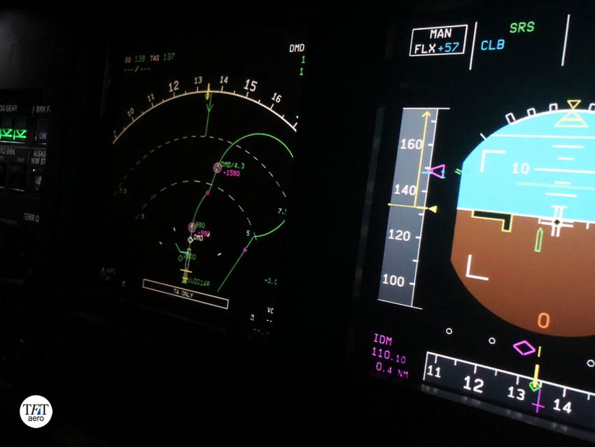
Indicated airspeed is displayed in the left column on the main flight display (PFD), and takeoff speeds V1, Vr and V2 are also displayed here. The navigation display shows TAS (true speed) and GS speeds. Let's look at each speed separately.

First, let's look at the instrument speed (IAS). If you ask the pilot during a flight, “What is our speed?” - it will first point you to the speed indicator to the left of the attitude indicator on the main flight display (PFD). When piloting, this is perhaps the most important speed; it characterizes the load-bearing properties of the glider at the current moment, regardless of the flight altitude. It is used to calculate takeoff, landing, V-stall and other key aircraft speeds.
How is indicated speed determined? Air pressure receivers (APRs), also known as Pitot tubes, are installed on airplanes. Based on the dynamic pressure measured with their help, the instrument speed is calculated.
An important point is that the formula for calculating the indicated speed uses a constant, the standard pressure at sea level. Do you remember that as altitude increases, pressure changes? Accordingly, the indicated speed coincides with the speed relative to the ground only at the surface.
Another interesting fact: What image comes to mind when you hear about aviation pioneers? A brown leather jacket, a helmet with goggles and a long white silk flowing scarf. According to some legends, the scarf was the first primitive indicator of instrument speed!

Now let's look at the top left corner of the navigation display. Our speed relative to the ground GS (Ground Speed) is displayed here. This is the same speed that is reported to passengers during the flight. It is determined primarily by data from satellite systems such as GPS. It is also used for control during taxiing, since at low speeds the pitot tubes do not create sufficient dynamic pressure to determine IAS.
A little to the right TAS (True Air Speed) is the true airspeed, the speed relative to the air surrounding the aircraft. All photographs were taken at approximately the same point in time. As you can see, the speeds vary significantly.
The IAS indicated speed is just under 340 knots. True airspeed TAS is 405 knots. Speed relative to the surface GS - 389. Now, I think you understand why they are different.
I also want to note the Mach number. Simplifying a little, this is the speed of a body relative to the speed of sound in a given medium. It is displayed under the indicated speed column and in our situation is 0.637.
Now let's discuss takeoff speeds. The three main takeoff speeds V1, Vr and V2, designations are standard for all aircraft that have more than one engine, from the little Beechcraft 76 to the giant Airbus A380, they are always located in this sequence. Let's imagine that our A320 is on the runway, the checklist has been completed, the controller's permission has been received, and we are completely ready for takeoff.
You move the engine controls to 40%, make sure the rpm is stable, and set the takeoff mode. The first speed to be reached will be V1 (148 knots in our conditions). This is the speed of decision making, in other words, after reaching V1, the takeoff can no longer be interrupted, including in the event of a serious failure. Even if you have an engine failure and V1 has already been reached, you must continue to take off. Before V1, in this situation, you initiate the aborted takeoff procedure, engage reverse, automatic braking is activated, spoilers are released, and you manage to stop before the end of the runway.
But everything is fine with us, the engines are working normally and, after V1, the pilot takes his hand off the engine control levers. Vr speed (rotate speed, 149 knots) is approaching. At this speed, the flying pilot pulls the control wheel (in our case, the sidestick) towards himself and raises the nose landing gear into the air.
At the same moment V2 arrived, in our situation Vr and V2 were calculated the same, but often V2 exceeds Vr. V2 - safe speed. In the event of failure of one of the engines, it will be V2 that will be supported; it guarantees a safe climb gradient. But, as you remember, everything is fine with us, the SRS mode is active, and the speed is V2+10 knots.
On the PFD during takeoff, V1 is indicated by a blue triangle, a magenta dot by Vr, and a magenta triangle by V2.
So, you have learned what takeoff speeds are and what they are eaten with, and now let’s find out how to prepare them, and what they depend on. We've now got our beautiful A320 in the air, but let's rewind the clock a little.
Let's imagine that we are preparing for departure, and it is time to calculate the speeds V1, Vr and V2. It's the 21st century, and the miracles of progress have given us an electronic flight briefcase (EFB - a specially trained iPad with the necessary set of software). What exactly information needs to be added to this briefcase so that the magic of ones and zeros can calculate our speeds? First of all, the length runway. You and I are preparing to take off from runway 14, right, of the capital's Domodedovo Airport. Its length is 3500 meters.
The moment of truth is coming. We enter our take-off weight and balance. We are deciding whether we can even take off from this runway, or whether we will have to leave a couple of hundred bottles from duty free and the four most obese passengers on earth :)
Since 3500 meters is more than enough for takeoff, we continue to enter data. Next in line are Airfield elevation above sea level, Wind component, Air temperature, Runway condition (wet/dry), Takeoff thrust, Flap position, Use of packs (air conditioning system) and anti-icing systems. Voila, the speeds are ready, all that remains is to add them to the MCDU.

Okay, we discussed calculating speeds using an electronic flight briefcase, but if you threw too many angry birds before the flight or, which is completely shameful for a pilot, played with tanks and discharged your miracle device? What if you are a representative of the school of obscurantism and deny progress? You are about to embark on a fascinating quest into the world of documents with scary names and the tables and graphs they contain.

First, we check whether we will take off from the selected runway: we open a graph in which the necessary variables are laid out along the axes. We move our finger to the intersection, and if the desired value is inside the graph, the attempt promises to be successful.
Next, take the next document and begin to calculate V1 Vr and V2. Based on the weight and the selected configuration, we obtain the speed values. Moving from plate to plate, we make adjustments, depending on the cell we add or subtract several nodes.
And so on over and over again until you get all the values, and there are many of them. Just like in first grade - he moved his finger and read the symbol. Very entertaining.

There is very little left: take off, turn on the autopilot at a thousand feet and wait just a little longer. And then the girls will bring a roller-coaster with food and you can immerse yourself in school memories. And the Airbus itself flies well, the main thing is not to interfere with it.
But we were daydreaming again. Meanwhile, we took off from the ground, maintained a speed of V2+10 knots and even managed to remove the landing gear so that they would not freeze. It's cold at the top, remember? We will gain altitude without applying noise reduction procedures, let everyone know that we have taken off! Once again, the old ladies on the upper floors will begin to vigorously cross themselves, and the children will joyfully point their fingers into the sky at our liner shining in the sun.
Before we could blink an eye, we reached an altitude of 1500 feet. It's time to put the Motor Control levers into Climb mode. The nose drops lower, and we begin to accelerate to S-speed, at which we remove the mechanization (Flaps 0), the next speed limit is 250 knots. 10,000 feet, the nose drops even lower, the speed continues to increase faster and the altitude slower. We turn off the Landing Lights, and the most impatient ones already have their hand ready to turn off the “fasten your seat belts” sign.
Top of climb, the specified flight level has been reached, the plane levels off, and we fly at cruising speed. It's time to replenish your calories!

Dinner at an altitude of several kilometers with panoramic view the surrounding area is wonderful. Yes, the food is not Michelin star worthy, but they will pay your bill! But all good things, as we know, tend to come to an end, so it’s time for us to decline. We lower the nose and begin our descent. After 10,000 feet the speed drops to 250 knots and we continue to decrease altitude.
It's time to move into the approach phase. Using the magic of the airbus (which itself calculated all the speeds), we slow down to Green dot speed (clean wing speed). Flying at this speed is as economical as possible for us, but you remember that everything good has the property...

We lower the flaps to the first position, the speed is reduced to S-speed. Next - flaps 2 and smoothly reach F-speed. Flaps 3 and finally full flaps, slowing down to Vapp. Vapp - minimum speed (VLS), but adjusted for wind and gusts (minimum 5 maximum 15 knots).
1000 feet, we check that the stabilized approach criteria are met, and if everything is normal, we continue our descent. Before touching down, the plane will demonstrate its attitude towards you by proclaiming “Retard! Retard! Retard!” (If you are not good at English-language name-calling, you can use the urbandictionary online dictionary). Set the throttle to idle and after a moment gently touch the runway.
Classification of flight speeds
According to the NLGS standards and established practice, when piloting and navigating aircraft, the following flight speeds are distinguished: true airspeed, ground speed, vertical speed, relative true airspeed (number M), indicated speed, indicated ground speed, indicated speed.
True air v ist is the speed of the aircraft relative to the air.
Ground speed w is the horizontal component of the aircraft’s speed relative to the Earth (Fig. 3.1).
From the navigation triangle it can be seen that the ground speed is equal to the geometric sum of the horizontal components v source and wind speed v V:
 . (3.1)
Vertical speed v H is the vertical component of the aircraft’s speed relative to the Earth or the rate of change of true altitude
 . (3.2)
Relative true air speed is the true speed divided by the speed of sound at a given temperature. It's called a number M(Mach number):
 . (3.3)
Indicated speed - the speed shown by the speed indicator, calibrated by the difference between the total and static air pressure
 , (3.4)
Where P n is taken taking into account the compressibility of air.
Indicated ground speed - indicated speed, corrected for instrumental error and aerodynamic correction:
 . (3.5)
Indicated speed is the indicated ground speed corrected for the compressibility correction associated with the difference in air pressure from the standard pressure at sea level:
 . (3.6)
True airspeed is related to indicated airspeed by the following relationship:
 , (3.7)
Where ρ H – air density at flight altitude N; ρ 0 – standard air density at sea level.
Often, in the technical literature, no distinction is made between instrument and indicator speeds. In theoretical calculations, the indicator speed is taken into account. Instrumented (indicated) speed is a purely piloting parameter. This parameter is used especially responsibly and often in such aircraft movement modes as take-off, take-off and landing. At each stage of aircraft movement, NLGS and ICAO standards assign characteristic values of indicated speed, which must be maintained to ensure safety. In this regard, there is a standard nomenclature for speeds:
Minimum take-off speed v min ER ( v MCG) is the speed at which, in the event of a sudden failure of a critical engine, it must be possible to control the aircraft using aerodynamic controls to maintain straight-line movement of the aircraft (ICAO designations are given in parentheses);
Minimum take-off speed v min EV ( v MCA) is the speed at which, in the event of a sudden failure of a critical engine, the aircraft must be controlled by aerodynamic controls to maintain straight-line motion of the aircraft;
Minimum lift-off speed v min OTR ( v MU) is set for all aircraft configurations accepted for takeoff within the range of alignments established by the flight operating regulations (FFR). In this case, the angle of attack should not exceed the permissible value α permissible;
- v Quality Control Department ( v EF) – speed at the moment of engine failure;
Decision speed v 1 is the take-off speed of the aircraft at which both a safe termination and a safe continuation of take-off are possible. The value of this speed is set in the Flight Manual and must satisfy the following conditions: v 1 ≥ v min ER; v 1 ≤ v p.st;
Speed at the moment of raising the front landing gear v p.st – the speed at which the steering wheel begins to deflect in the “toward” direction to increase the pitch angle during the take-off run;
Safe takeoff speed v 2 must be no less than: 1.2 v C1 in takeoff configuration; 1.1 v min EV; 1.08 vα additional also in take-off configuration;
Lift-off speed v OTR ( v LOF) – the speed of the aircraft at the moment its main landing gear lifts off the runway surface at the end of the take-off run;
Speed at the start of mechanization cleaning on takeoff v 3 ;
Speed in flight configuration at takeoff v 4 . It must be no less than 1.3 v C1 and 1,2 v min EV;
Minimum evolutionary approach speed v min ED ( v MCL) - the speed at which, in the event of a sudden failure of a critical engine, it must be possible to control the aircraft using only aerodynamic controls;
Maximum approach speed v Salary max ;
Approach speed v Salary max ( v REF);
- v C ( v S) – stalling speed, the minimum speed of the aircraft when braking to the angle of attack αpre;
- v C1 ( v S 1) – stalling speed of the aircraft when the engines are operating in idle mode;
- vα add ( v C y additional) speed at permissible angle of attack at n y = 1;
- v max E – maximum operating speed. This speed should not be deliberately exceeded by the pilot in normal operation in all flight conditions;
- v max max – calculated maximum speed. It is set based on the possibility of unintentionally exceeding it. v max max - v max ≥ 50 km/h. If this speed is exceeded, a catastrophic special situation cannot be ruled out.
3.2. Device for measuring indicator (instrument) speed
The indicated airspeed indicator is used as a flight instrument to measure the aerodynamic forces acting on an aircraft in flight. It is known (2.18) that the aerodynamic lift force is determined by the formula
 .
.
As the angle of attack increases α the lifting force increases up to its limit value. The greater the angle of attack, the less speed is needed to keep the aircraft in the air. As follows from paragraph 3.1, each flight mode corresponds to a certain minimum speed value at which the aircraft can still remain in the air. For example, the condition for horizontal flight is that the weight of the aircraft and the lift force are equal

 ,
,
Where G- weight of the aircraft. From here we find the speed of horizontal flight
 .
.
The indicated airspeed indicator is one of the most important flight instruments; it gives the pilot the opportunity to prevent the aircraft from falling at low speeds and being destroyed at high speeds due to excessively large aerodynamic forces. In its physical meaning, the instrument speed indicator does not measure speed, but the difference between total and static pressures (3.4), or the speed pressure of oncoming air, which depends on both the speed and the density of the air. Since it is more familiar and easier for a pilot to remember the characteristic values of speed rather than pressure, the indicator is calibrated in units of speed.
By definition (3.4), the indicator (instrumented) velocity is based on the manometric method, that is, on measuring the difference between total and static pressure.
The relationship between speed, total pressure and static pressure is determined using Bernoulli's equation applied to the air flow perceived by the air pressure receiver (Fig. 3.2). At critical point 2, the air speed drops to zero. Let us write this equation, without delving into its derivation, for the case of incompressible air:
 , (3.8)
Where v 1 and v 2 – flow velocity in sections 1 and 2 in m/s; P 1 and P 2 – air pressure in sections 1 and 2 in kg/m2; ρ 1 and ρ 2 – air density in sections 1 and 2 in kg s 2 /m 4.
Since cross section 1 is taken in an unperturbed medium, then the speed v 1 equals true airspeed v ist, pressure P 1 equals static pressure P Art. Pressure P 2 at the point of complete braking is equal to the full pressure P n, since at this point the speed v 2 is equal to zero. Considering that for an incompressible medium ρ 1 = ρ 2 = ρ , after appropriate replacement in equation (3.8), we obtain
 (3.9)
(3.9)
or  kg/m2. (3.10)
Taking into account the compressibility of the air flow, equation (3.10) takes the form:

or finally  , (3.11)
Where  ; qсж – velocity pressure taking into account air compressibility.

Rice. 3.3. Pressure dependence P dynes of flow rate:
1 – without taking into account air compressibility; 2 – taking into account air compressibility
From Figure 3.3 it is clear that taking into account the compressibility of the flow leads to an additional increase in dynamic pressure (line 2). In this case, the dependence of dynamic pressure on air flow parameters has the form:
 , (3.12)
Where k– heat capacity ratio; g– acceleration of gravity; R– gas constant equal to 29.27 m/deg; T– temperature of the undisturbed atmosphere in o K. Using formula (3.12), the indicators of the indicated and true airspeed are calibrated.
To calibrate the indicator speed indicator, values corresponding to normal conditions at sea level are taken: R st = R o st = 760 mm Hg. Art. (10332.276 kg/m2), T = T o = 288 o K ( t= +15 o C), R= 29.27 m/deg, mass density ρ o = 0.124966 kg s 2 /m 4, k= 1.405. After this, it turns out that the indicator speed according to formulas (3.11) and (3.12) depends only on the dynamic pressure R din. For practical use, there are standard tables from which the value of dynamic pressure can be determined for each speed.
Particular attention should be paid to the fact that the indications of the indicated airspeed indicator do not depend on the static pressure, and therefore on the altitude of the aircraft. In this regard, they say that the indicator (as well as the sensor and signaling device) of the indicated (instrument) speed does not have a methodological error from changes in flight altitude. This is a valuable quality of the device, ensuring flight safety regardless of altitude. It is important that there is always the required value of the velocity pressure at any height.
In Fig. 3.4 shows a schematic diagram of an instrument speed indicator with separate pressure receivers R n and R Art. Total pressure R n = R d + R st enters the sealed cavity of the pressure gauge box 5 from the receiver 7 through the pneumatic line 6. Pressure enters the sealed cavity of the housing 3 from the receiver 1 through the pneumatic line 2 R Art. Under the influence of pressure difference R P - R st = R d + R st - R st = R d the membrane of the pressure gauge box bends and turns the arrow relative to the indicator - scale 4.

Rice. 3.4. Schematic diagram of the instrument speed indicator: 1 – static pressure receiver R st; 2 – static pressure pneumatic line; 3 – body; 4 – indicator; 5 – pressure gauge box; 6 – full pressure pneumatic line; 7 – full pressure receiver R P

Rice. 3.5. Block diagram of the instrument speed indicator: 1 – pressure receiver R n and R st; 2 – pneumatic line R P; 3 – pneumatic line R st; 4 – channel sedimentation filters R P; 5 – channel sedimentation filters R st; 6 – box cavity; 7 – body cavity; 8 – conditional link for the formation of dynamic pressure R d; 9 – decisive device; 10 – indicator
Figure 3.5 shows a block diagram of the instrument speed indicator, compiled according to its circuit diagram (Figure 3.4). Let's take a closer look at the role of each link in the operation of the speed indicator.
Full pressure receiver
For the indicator speed indicator to work, according to the principle of its operation, it is necessary to perceive total and static pressure in flight. In the practice of aircraft instrument making, separate receivers for total and static pressures are used (Fig. 3.4). Pressures must be perceived accurately, since dynamic pressure depends on the square of speed.
The total pressure receiver (TPR) is designed to perceive only the total pressure of the oncoming air flow. The term “total pressure” means the pressure per unit surface of a body whose plane is perpendicular to the direction of the oncoming flow. For PPD, a cylindrical body is used, in the center of which a through hole is made.
From Figures 3.6 and 3.7 it is clear that complete braking of the oncoming air flow will only be at the point A. If in the cylinder near the point A make a hole, then along its cavity a pressure equal to the full R n = R st + R d. Like any instrument, PPD has a perception error R n, associated with the imperfection of its design.
From the definition of total pressure itself, it follows that the best location of the PPD relative to the air flow is when the cross-sectional plane of the receiver inlet is perpendicular to the velocity vector. In this case, the receiver error will be caused only by flow losses in the channel cavity R p (Fig. 3.8). This installation condition is equivalent to when the longitudinal axis of the PPD receiver coincides with the direction of the air flow.
But even in this case, the receiver has an error of the order of 2%, which is defined as the ratio of the absolute value of the error Δ R n to velocity pressure 0.5 ρ v 2 .
| Rice. 3.8. Dependence of coefficient ξ receiver PPD from speed at α = β = 0 |

Under these conditions, formula (3.11) can be rewritten in the form
 , (3.13)
Where ξ – receiver coefficient at α = β = 0. If the PPD setting is such that α ≠ 0, β ≠ 0, then additional angular errors Δ appear R n = ±Δ R P f(α ) and Δ R n = Δ R P f(β ). The next reason for the occurrence of RPD error is the skew of the air flow at the location where the receiver is installed on board the aircraft. This error is normalized by NLGS within no more than 10 km/h or 3% (whichever is greater) over the entire speed measurement range. By choosing the installation location on board the aircraft, due to design techniques and calibration in wind tunnels, the RPM error can be reduced to ± (0.005 - 0.01) q.
Speed range from 40 to 1100 km/h; weight 0.17 kg; error in the speed range up to 150 km/h no more than ± 0.05 q at corners α = β = ± 25 o; error at speeds over 150 km/h and angles α = β = ± 20 o no more than ± 0.025 q; DC heating with power up to 135 W.

Rice. 3.9. Design of the PPD-4 receiver: 1 – tip; 2 – drainage hole;
3 – heating element; 4 – hole; 5 – cheek; 6 – base; 7 – socket; 8 – fork; 9 – wire; 10 – fitting

Rice. 3.10. Appearance full pressure receiver PPD-9V
Static pressure receiver
Static pressure is understood as the pressure that would exist at a given point in a medium undisturbed by the device if the device were moving at the speed of the flow. Static pressure in a medium at rest is called barometric or atmospheric pressure and is measured by a barometer. It is measured as absolute pressure, measured from absolute zero pressure. For measuring static pressure R This requires a device of a design that would not distort the flow at the point under study. When measuring pressure R The device moves relative to the air, and this, according to the laws of aerodynamics, leads to air disturbance. In this case, the shape of the device - receiver R Art plays a major role on the measurement accuracy. The measured pressure will be the sum of the pressure in the flow undisturbed by the device and the additional pressure caused by the flow around the device, and depends on its shape. The flow conditions around the device may be such that the measured pressure may be greater or less than its true value (Fig. 3.11).

Rice. 3.11. Distribution of the pressure coefficient for a typical subsonic distribution along the aircraft fuselage line: 1 – only along the free fuselage; 2 – along the fuselage along with planes and tail surfaces
Most commonly measured R A static probe (static hook) is used. It is a hollow cylindrical tube with a diameter d with a streamlined closed toe.
There are small diameter holes on the side surface of the tube. To increase the accuracy of measurements in the device, increase the distance l 1 from the receiving holes to the toe and in the other direction - l 2 to the holder. The following ratios are recommended: l 1 = 3d, l 2 = 8δ .
In aviation, the role of a hollow cylindrical tube is often used by the aircraft fuselage itself (at subsonic levels), in which receiving holes are made (Fig. 3.13).
For convenience and reliability of perception R Instead of holes in the fuselage, a standard plate with holes is used. Together with the housing, it forms a device for sensing static pressure (Fig. 3.14). On the fuselage, select places to install the slab receiver where the smallest deviations of line 2 in Fig. 3.11 from midline 0-0. The receiver plate is installed flush with the skin on the aircraft.

Rice. 3.15. Appearance of the tiled static pressure receiver PDS-V3 speed range when perceived R speed up to 450 km/h; weight 0.25 kg; heating with DC voltage 27 V at power up to 60 W
In addition to the considered receivers R n and R Combination receivers called PVD have found widespread use in aviation. This device combines two devices: receivers R n and R st (Fig. 3.16). Separate receivers are used mainly at subsonic flight speeds. At supersonic flight speeds, the flow around the fuselage is so complex and unpredictable that it is impossible to find places to install pressure receivers.

Rice. 3.16. Schematic diagram of a PVD type receiver: 1 – total pressure chamber; 2 – opening of the static pressure chamber; 3 – static pressure chamber; 4 – static pressure pipeline; 5 – full pressure pipeline
On supersonic aircraft, the PVD is carried out using a rod into the undisturbed space in front of the aircraft. In the same way, the PVD is installed on a helicopter.
aviation bombs and containers, ... special equipment, devices, equipment, medical...